
Cable connector having fastening member

a technology of fastening member and cable connector, which is applied in the direction of television connector, coupling device connection, electrical apparatus, etc., can solve the problems of increasing the transverse size of the connector, influent on normal signal transmission, and increasing the density of the connector, so as to improve the fastening member and reduce the size

Inactive Publication Date: 2007-05-08
HON HAI PRECISION IND CO LTD
View PDF4 Cites 10 Cited by
  • Summary
  • Abstract
  • Description
  • Claims
  • Application Information

AI Technical Summary

Benefits of technology

The present invention provides a cable connector with an improved fastening member and reduced size. The cable connector includes an insulative housing with a plurality of passageways and contacts assembled in the passageways. A cable with conductors is connected to the contacts to form junctions. A cover encloses the rear end of the housing and the junctions between the contacts and the cable. The cover has a mating face with a longer edge and a projection on the outer periphery of the cover with a front surface coplanar with the mating face of the cover. The projection defines a fastening hole therethrough. A fastening member is fixed to the cover and couples with the fastening hole for fastening the cable connector to a coupling device.

Problems solved by technology

However, when such type HDMI cable assembly is usually used out of a chassis, after the HDMI cable assembly has been used for a long time, or when inaccidental pulling force is exerted to the cable, it often leads to the HDMI cable assembly apart from the mating connector, thus influenting the normal signal transmission.
However, this manner certainly increases the transverse size of the connector.
With the increase of the numbers of different connector interfaces arranged on the mounting board, the distribution of connector correspondingly become more and more densely, establishing screws at lateral portions is not benefit for connectors' distribution.

Method used


Image

  • Cable connector having fastening member
  • Cable connector having fastening member
  • Cable connector having fastening member

Examples


Embodiment Construction

[0015]Reference will now be made to the drawing figures to describe the present invention in detail.

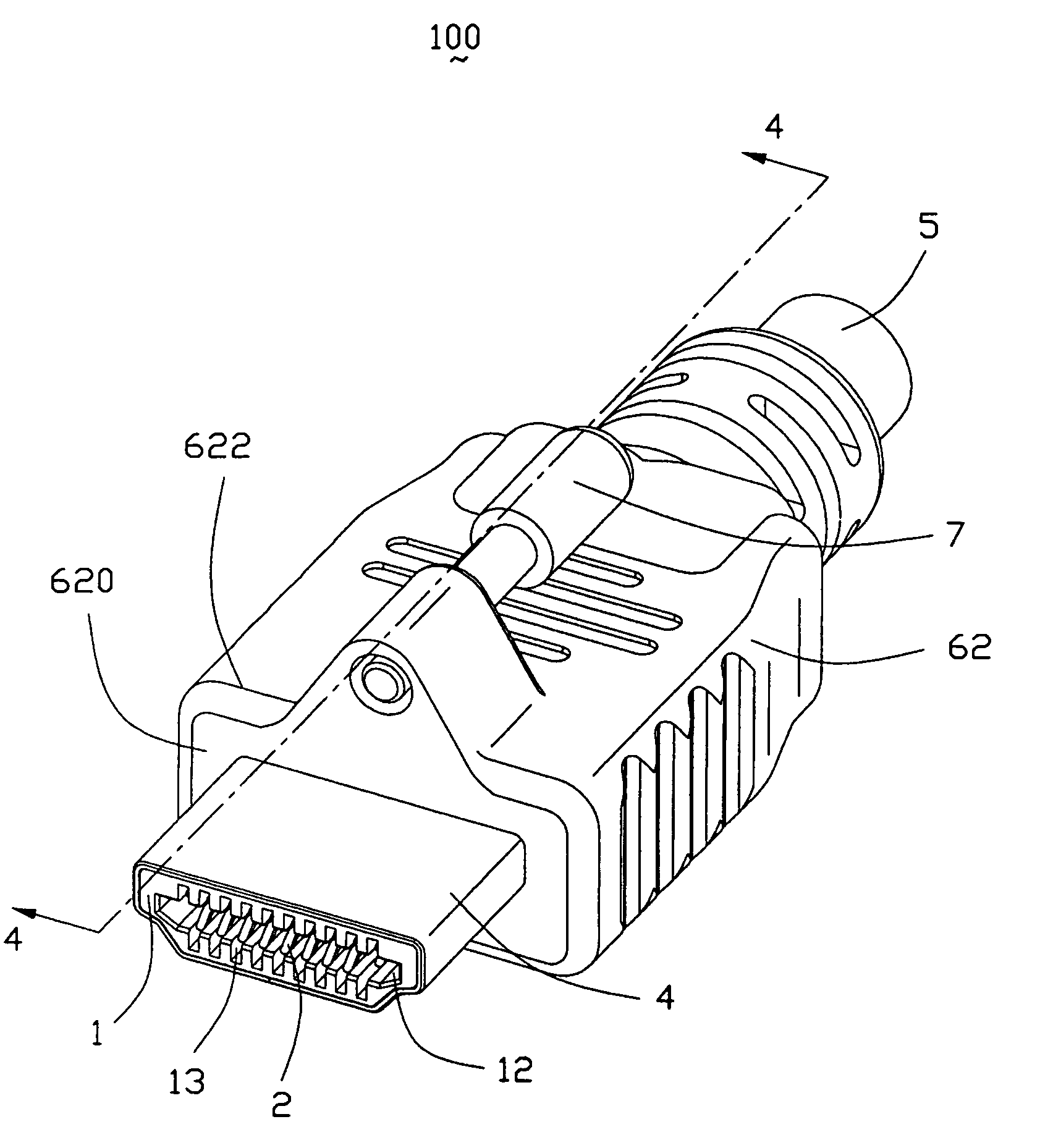
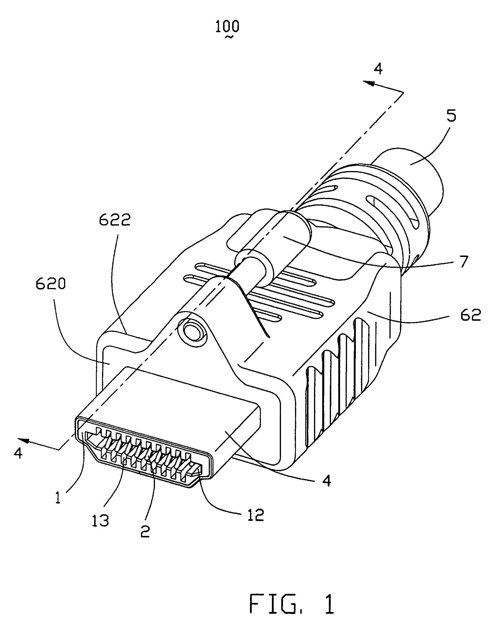
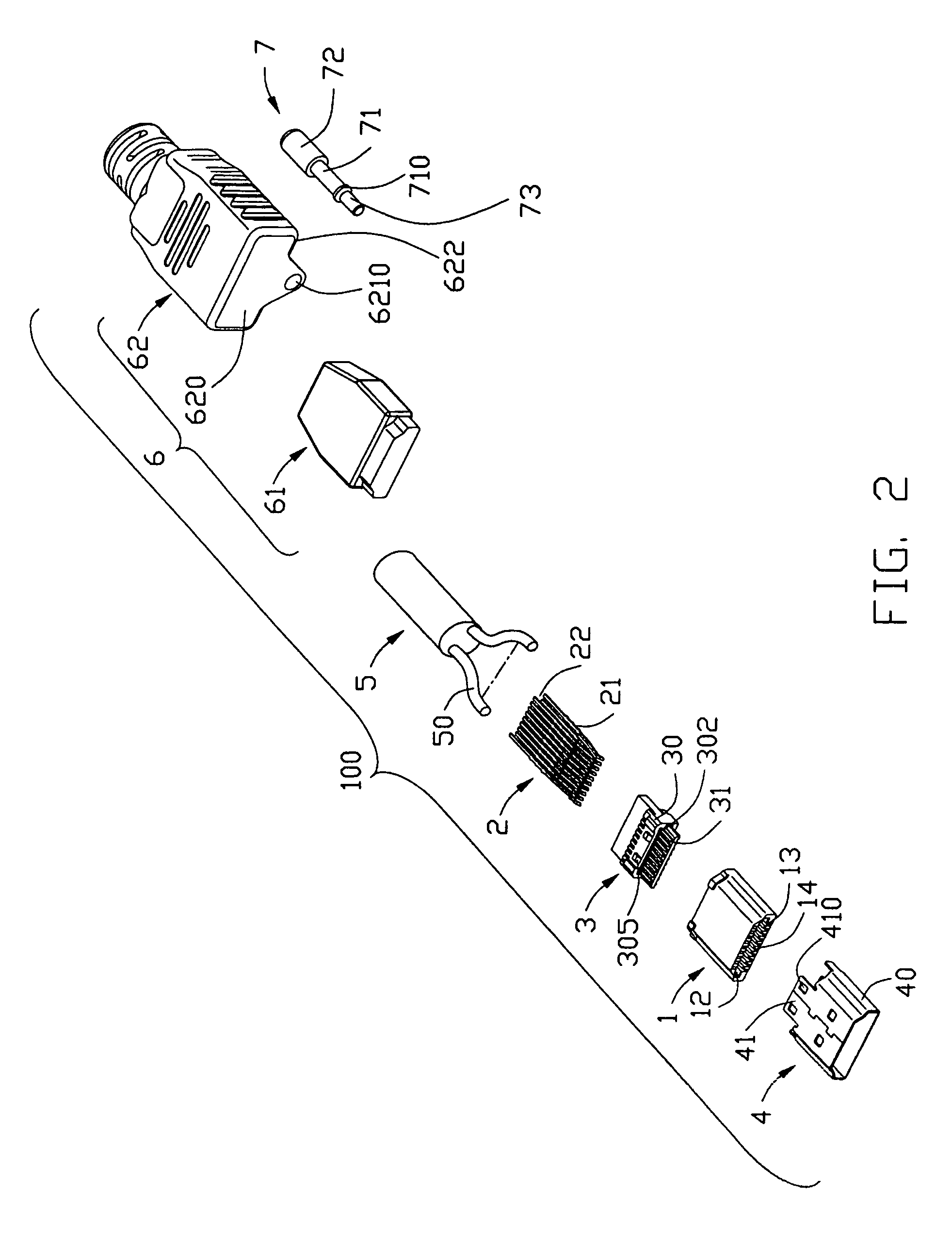
[0016]Referring to FIGS. 1–4, a cable connector 100 in accordance with the present invention is according to HDMI (High-Definition Digital Multimedia Interface) standard and comprises an insulative housing 1, a plurality of contacts 2 assembled to the insulative housing 1, a spacer 3 sealing the rear end of the insulative housing 1, a conductive shell 4 shielding the insulative housing 1, a cable 5 electrically connecting with the contacts 2, a cover 6 comprising an inner mold 61 and an outer mold 62, and a fastening member 7 assembled to a fastening hole 6210 located on the cover 6.

[0017]The insulative housing 1 defines a front portion 14 mating with a complementary connector and a rear portion 15 coupling with the shell 4 and the spacer 3. The insulative housing 1 comprises an upper wall 10, a lower wall 11 and a receiving space 12 formed therebetween. The upper wall 10 parallels th...


PUM


Abstract

A cable connector (100) in accordance with the present invention includes an insulative housing (1) defining a number of passageways (13) therethrough, a number of contacts (2) assembled to the insulative housing and respectively received in the passageways, a cable (5) including a number of conductors (50) respectively electrically connecting with connecting portions of the contacts to form a number of junctions, a cover (6) enclosing the rear end of the housing (1) and junctions between the contacts (2) and the cable (5), the cover (6) having a mating face (620) having at least a longer edge (622) and a projection (621) formed on outer periphery of the cover (6) with front surface coplanar with the mating face of the cover the projection and defining a fastening hole (6210) therethrough; and a fastening member (7) inserted into the cover and coupling with the fastening hole (6210) for fastening the cable connector (100) to a coupling device.

Description

BACKGROUND OF THE INVENTION[0001]1. Field of the Invention[0002]The present invention generally relates to a cable connector, and more particularly to a cable connector having fastening member.[0003]2. Description of Related Art[0004]To satisfy current particular commands in market, in April 2002, Hitachi, Panasonic, Phillips, Sony, Thomason, Toshiba and Silicon Image et al. found High-definition Digital Multimedia Interface (HDMI) Association to develop new standard for high-definition video and channel audio. An HDMI cable assembly comprises an insulative housing, a plurality of contacts assembled to the insulative housing, a conductive shell surrounding the insulative housing, and a cable electrically connecting with the contacts. Referring to FIG. 5, a conventional HDMI cable assembly has a mating portion 101. When the cable assembly mates with a mating connector, the mechanism connection of the cable assembly and the mating connector only depends on the friction produced betwee...

Claims


Application Information

Patent Timeline
Patent Type & Authority Patents(United States)
IPC IPC(8): H01R13/627
CPCH01R13/6215H01R2201/18H01R12/725
Inventor KUO, PETER
Owner HON HAI PRECISION IND CO LTD
Learn More