Dual tip probe
a probe tip and probe technology, applied in the field of test probes, can solve problems such as affecting the precision and achieve the effect of improving the accuracy of the probe tip placemen
- Summary
- Abstract
- Description
- Claims
- Application Information
AI Technical Summary
Benefits of technology
Problems solved by technology
Method used
Image


Examples
first embodiment
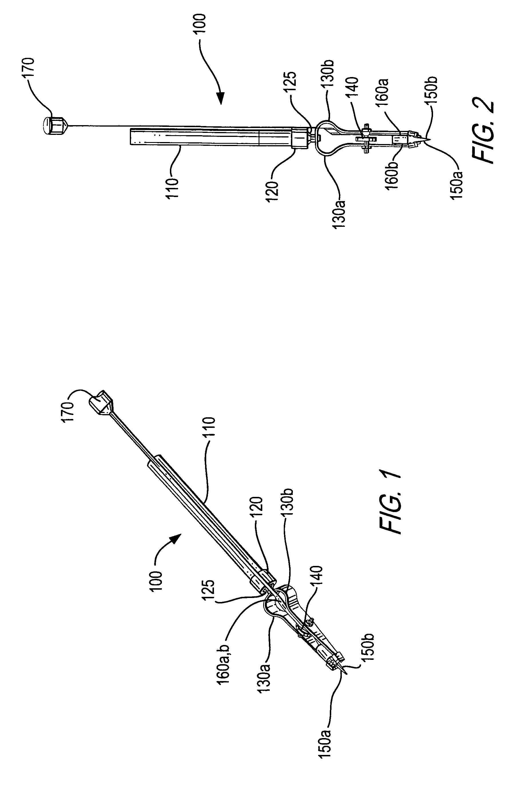
[0027]Referring first to FIG. 1, a dual tip probe 100 constructed in accordance with the invention is shown. Probe 100 includes a rigid member 110 having a proximate end and a distal end, and a pair of probe tips 150a, 150b. A locking mechanism 120 is fixed to the distal end of rigid member 110 and is operative to selectively lock the positioning of a joint 125. A pair of probe support arms 130a, 130b are in turn fixed to a selectively positionable portion of joint 125. These support arms meet at joint 125, and are shaped to support probe tips 150a, 150b in close proximity to each other. An arm positioning mechanism 140 selectively positions arms 130a, 130b relative to each other, and therefore in turn positions probe tips 150a, 150b relative to each other. Through the operation of arm position mechanism 140, this relative positioning between the probe tips may be adjusted. Finally, probe tips 150a, 150b are maintained in electrical contact with a standard connector 170 (which may b...
second embodiment
[0028]Referring next to FIG. 3, a dual tip probe constructed in accordance with the invention is shown. For clarity, the probe is shown without the probe tips, flex circuits, or standard connector thereon. However, it should be understood that these features are intended to be included similarly to those shown in FIGS. 1 and 2. As is shown in FIG. 3, a dual tip probe 300 includes a rigid member 310 having a proximate end and a distal end. A locking mechanism 320 is fixed to the distal end of rigid member 310 and is operative to selectively lock the positioning of a joint 325. A pair of probe support arms 330a, 330b are in turn fixed to a selectively positionable portion of joint 325. These support arms meet adjacent joint 325, and are shaped to support a pair of probe tips (not shown) in close proximity to each other. An arm positioning mechanism 340 selectively positions arms 330a, 330b relative to each other, and therefore in turn positions the probe tips relative to each other. T...
third embodiment
[0034]Referring next to FIG. 6, a dual tip probe constructed in accordance with the invention is shown. As in FIG. 3, for clarity, the probe is shown without the probe tips, flex circuits, or standard connector thereon. However, it should be understood that these features are intended to be included similarly to those shown in FIGS. 1 and 2. As is shown in FIG. 6, a dual tip probe 600 includes a rigid member 610 having a proximate end and a distal end. A locking mechanism 620 is fixed to the distal end of rigid member 610 and is operative to selective lock the positioning of a joint 625. A pair of probe support arms 330a, 330b are in turn fixed to a selectively positionable portion of joint 625. These support arms meet adjacent joint 625, and are shaped to support a pair of probe tips (not shown) in close proximity to each other. Arm positioning mechanism 340 selectively positions arms 330a, 330b relative to each other, and therefore in turn positions the probe tips relative to each...
PUM
 Abstract
Description
Claims
Application Information
 - R&D
- Intellectual Property
- Life Sciences
- Materials
- Tech Scout
- Unparalleled Data Quality
- Higher Quality Content
- 60% Fewer Hallucinations
Browse by: Latest US Patents, China's latest patents, Technical Efficacy Thesaurus, Application Domain, Technology Topic, Popular Technical Reports.
© 2025 PatSnap. All rights reserved.Legal|Privacy policy|Modern Slavery Act Transparency Statement|Sitemap|About US| Contact US: help@patsnap.com