
Data transmission apparatus, photoelectric conversion circuit and test apparatus

a technology of photoelectric conversion circuit and data transmission apparatus, which is applied in the direction of moving filter element filter, filtration separation, separation process, etc., can solve the problems of skew between channels, high power consumption, and restricted data communication speed

Inactive Publication Date: 2007-04-24
ADVANTEST CORP
View PDF21 Cites 4 Cited by
  • Summary
  • Abstract
  • Description
  • Claims
  • Application Information

AI Technical Summary

Benefits of technology

The present invention provides a data transmission apparatus, a photoelectric conversion circuit, and a test apparatus that can overcome the drawbacks of conventional art. The data transmission apparatus includes a transmitting unit, a photoelectric conversion circuit, and a variable setting unit for generating predetermined electric communication data in response to the level of optical communication data. The photoelectric conversion circuit includes a light receiving unit and a signal generating unit for generating the electric communication data. The variable setting unit can set the photoelectric conversion circuit based on the transmission delay time, attenuation of the optical communication data, and the efficiency of the electric communication data. The test apparatus includes a pattern generating unit, a waveform adjusting unit, a test head, and a data transmission apparatus for transmitting data between the waveform adjusting unit and the test head. The data transmission apparatus includes a transmitting unit for converting and sending the test signal in optical communication data. The photoelectric conversion circuit includes a photodiode and a variable current supply for generating the current to offset the current generated by the photodiode. The technical effects of the invention include improved data transmission and testing accuracy.

Problems solved by technology

In accordance with the trend towards high speed data communication, however, there occurs a problem of skew between the channels.
For example, due to the skew, the speed of data communication is restricted.
In the conventional data transmission apparatus, a complicated framing circuit and a coding circuit are provided to the transmitter side, whereas an encoding circuit being provided to the receiver side, to reduce the skew, but there occurs a problem that the power consumption is high, and the response decreases.

Method used


Image

  • Data transmission apparatus, photoelectric conversion circuit and test apparatus
  • Data transmission apparatus, photoelectric conversion circuit and test apparatus
  • Data transmission apparatus, photoelectric conversion circuit and test apparatus

Examples


Embodiment Construction

[0029]The invention will now be described based on the preferred embodiments, which do not intend to limit the scope of the present invention, but exemplify the invention. All of the features and the combinations thereof described in the embodiment are not necessarily essential to the invention.

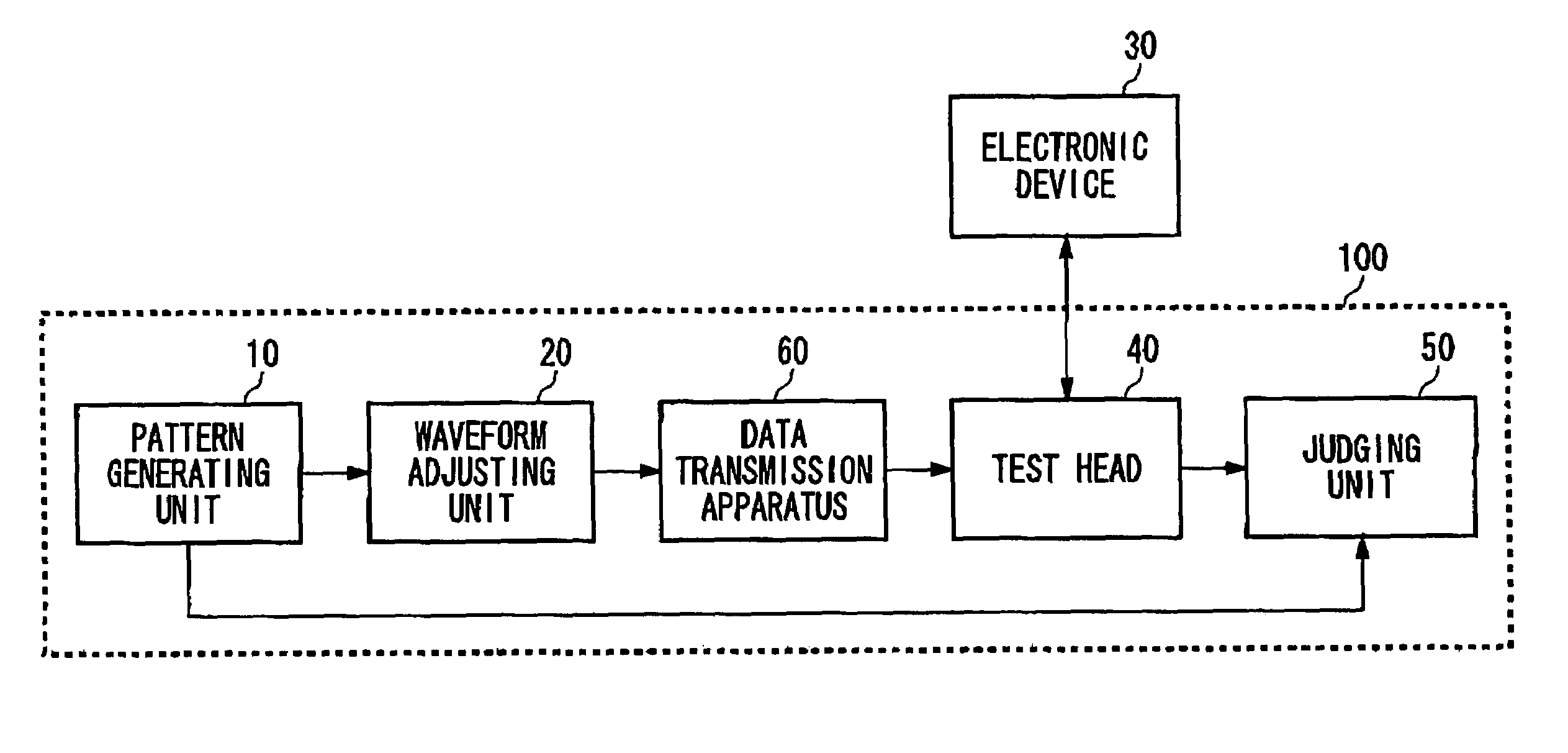
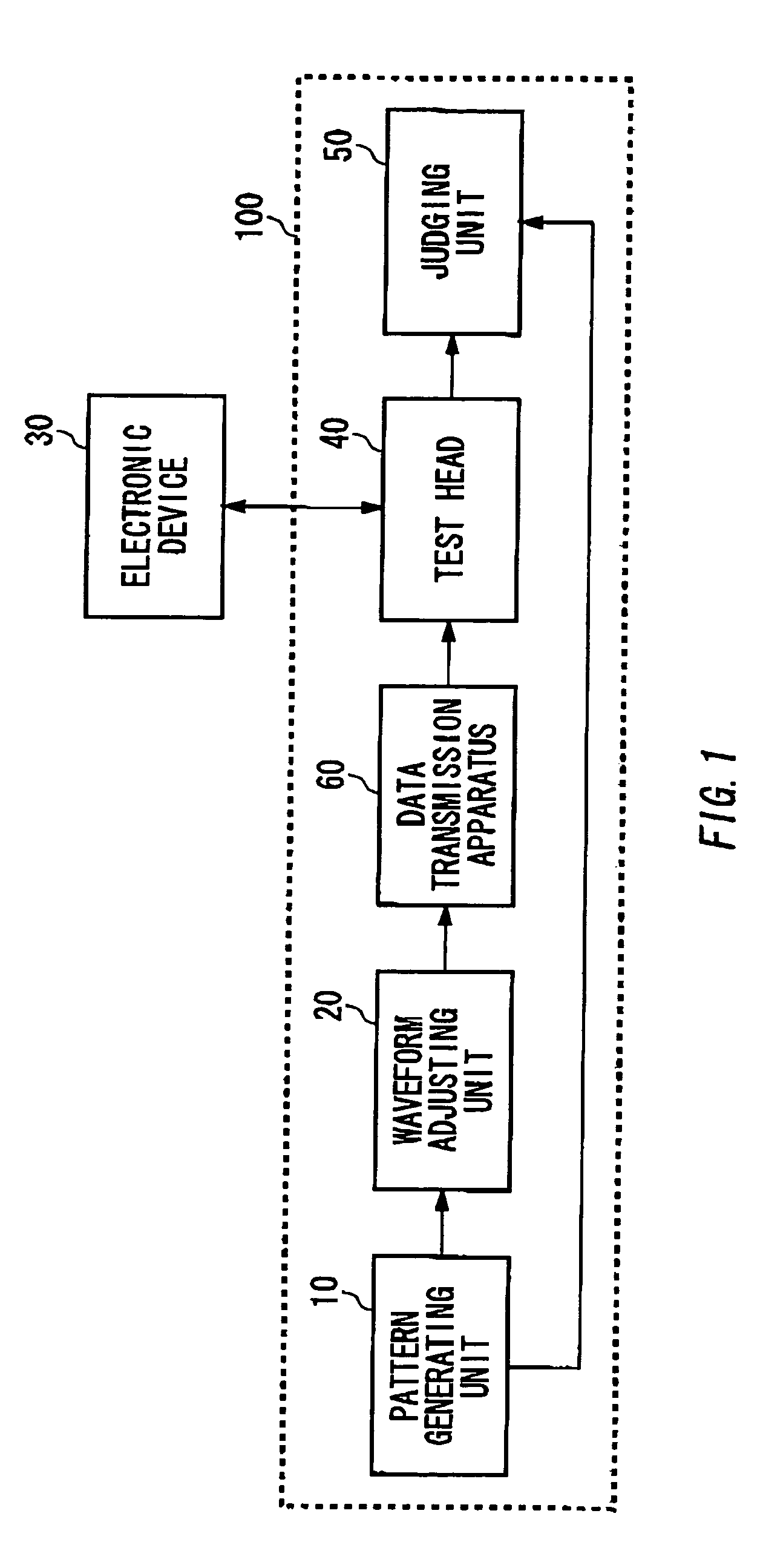
[0030]FIG. 1 shows an example of the configuration of a test apparatus 100 related to the present invention. The test apparatus 100 performs the test of an electronic device 30. The test apparatus 100 includes a pattern generating unit 10, a waveform adjusting unit 20, a data transmission apparatus 60, and a judging unit 50.

[0031]The pattern generating unit 10 generates a test signal for the test of the electronic device 30, and supplies it to the waveform adjusting unit 20. And the pattern generating unit 10 generates an expected signal which the electronic device 30 is supposed to output when receiving the test signal, and supplies it to the judging unit 50.

[0032]The waveform adjusting unit...


PUM

PropertyMeasurementUnit
currentaaaaaaaaaa
electric communicationaaaaaaaaaa
optical communicationaaaaaaaaaa

Abstract

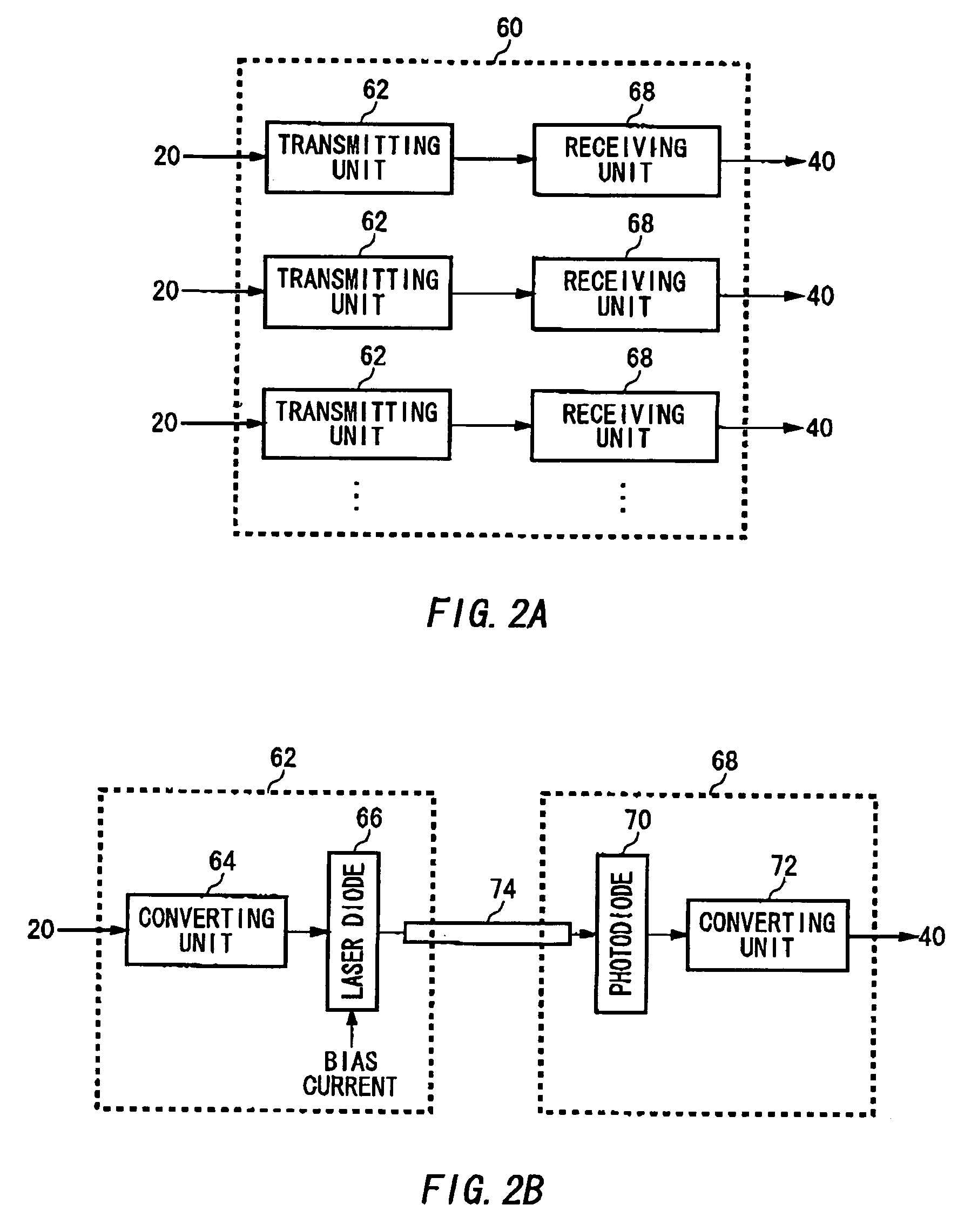
The data transmission apparatus for performing data communication based on optical transmission includes a transmitting unit for converting and sending electric communication data, which is to be transmitted, into optical communication data, and a photoelectric conversion circuit for receiving the optical communication data and converting the received optical communication data into electric communication data, wherein the photoelectric conversion circuit includes a photodiode for generating a current based on the optical communication data, and a variable current supply for subtracting a predetermined current from the current generated by the photodiode. In addition, a bias current of a laser diode of each transmitting unit is set to a current larger than a laser oscillation threshold current so as to reduce the deviation of a light emission delay time of each laser diode.

Description

[0001]The present application is a continuation application of PCT / JP02 / 10245 filed on Oct. 2, 2002, which claims priority from a Japanese Patent application No. 2001-312050 filed on Oct. 9, 2001, the entire contents of which are incorporated herein by reference for all purposes.BACKGROUND OF THE INVENTION[0002]1. Field of the Invention[0003]The present invention relates to a photoelectric conversion circuit for performing photoelectric conversion, a data transmission apparatus for performing data transmission, and a test apparatus for testing an electronic device. More particularly, the present invention relates to a data transmission apparatus based on optical transmission.[0004]2. Related Art[0005]In data communication, the trend towards higher speed and larger capacity is recently significant. In short distance transmission such as indoor transmission, parallel optical transmission is now the prevailing method, when performing large-sized data communication at high-speed. A data...

Claims


Application Information

Patent Timeline
Patent Type & Authority Patents(United States)
IPC IPC(8): H04B10/04H04B10/40G01J1/44H04B10/07H04B10/2507H04B10/50H04B10/54H04B10/60H04B10/69
CPCH04B10/504H04B10/69G01J1/44H04B10/5561H04B10/07H04B10/50
Inventor ONO, ATSUSHIOKAYASU, TOSHIYUKI
Owner ADVANTEST CORP
Learn More