
Spherical aberration compensation by wavelength

a wavelength and aberration compensation technology, applied in the field of optical read/write system, can solve the problems of affecting the accuracy of the signal, and other undesirable elements, and achieve the effect of minimizing the spherical aberration and the present spherical aberration

Inactive Publication Date: 2007-04-24
ALLIANCE STORAGE TECH
View PDF27 Cites 0 Cited by
  • Summary
  • Abstract
  • Description
  • Claims
  • Application Information

AI Technical Summary

Benefits of technology

[0009]The present invention minimizes the spherical aberration caused by wavelength error of an objective lens by matching lenses and lasers in such a manner so that, in combination, the errors of each offset each other. Thus, this invention uses the chromatic sensitivity of the objective lens to minimize the spherical aberration present.

Problems solved by technology

As with any data read / write system, optical systems are vulnerable to flaws and other manufacturing variations, dirt, scratches, and other factors that may result in degraded performance.
However, other undesirable elements are prevalent and have heretofore gone uncorrected.
Two particularly troublesome elements pertain to the thickness of the objective lens and the frequency at which the laser beam operates.
Spherical aberrations cause concentric rings to form around the focused spot on the media, making it difficult to read the stored information.
Because all manufacturing processes result in components having certain tolerances and variations, spherical aberrations are difficult to avoid using an economical manufacturing process.
Moreover, the relatively small radius of the curve used in objective lenses makes spherical aberrations even more difficult to avoid, control and predict.
Variations in the wavelength of the laser diode light source are equally as difficult to control and predict using economically feasible manufacturing techniques.

Method used


Image

  • Spherical aberration compensation by wavelength
  • Spherical aberration compensation by wavelength
  • Spherical aberration compensation by wavelength

Examples


Embodiment Construction

[0016]Referring now to FIGS. 2 and 3, there is shown a method 100 of the present invention, usable to minimize the spherical aberration effects of two components, namely an objective lens and a laser, of an optical media device due to manufacturing imperfections. It can be seen that the method 100 begins at 110 with identifying a Z8 slope characteristic of the lens shape for the objective lens. The slope of Z8 versus wavelength is very similar for all lenses of the same design, regardless of the slight variations in thickness. FIG. 3 provides an example of a plot of Z8 versus wavelength for ten lenses, L1 through L10, all of the same design but having different thickness variations. It can be seen that all of the plotted lines have the same slope.

[0017]At 120, a test is performed on the manufactured objective lens to determine the magnitude of spherical aberration, known as the Z8 term, at a predetermined wavelength for which the lens is designed. This is done using a standard laser...


PUM

PropertyMeasurementUnit
wavelengthaaaaaaaaaa
wavelength varianceaaaaaaaaaa

Abstract

A method for minimizing spherical aberration in an optical read / write drive caused by variances in lens thickness and laser wavelength. The method provides an economic solution that pairs objective lenses with laser diodes such that the spherical aberration caused by the objective lens is offset by the spherical aberration caused by the laser wavelength, thereby minimizing or completely canceling the overall spherical aberration.

Description

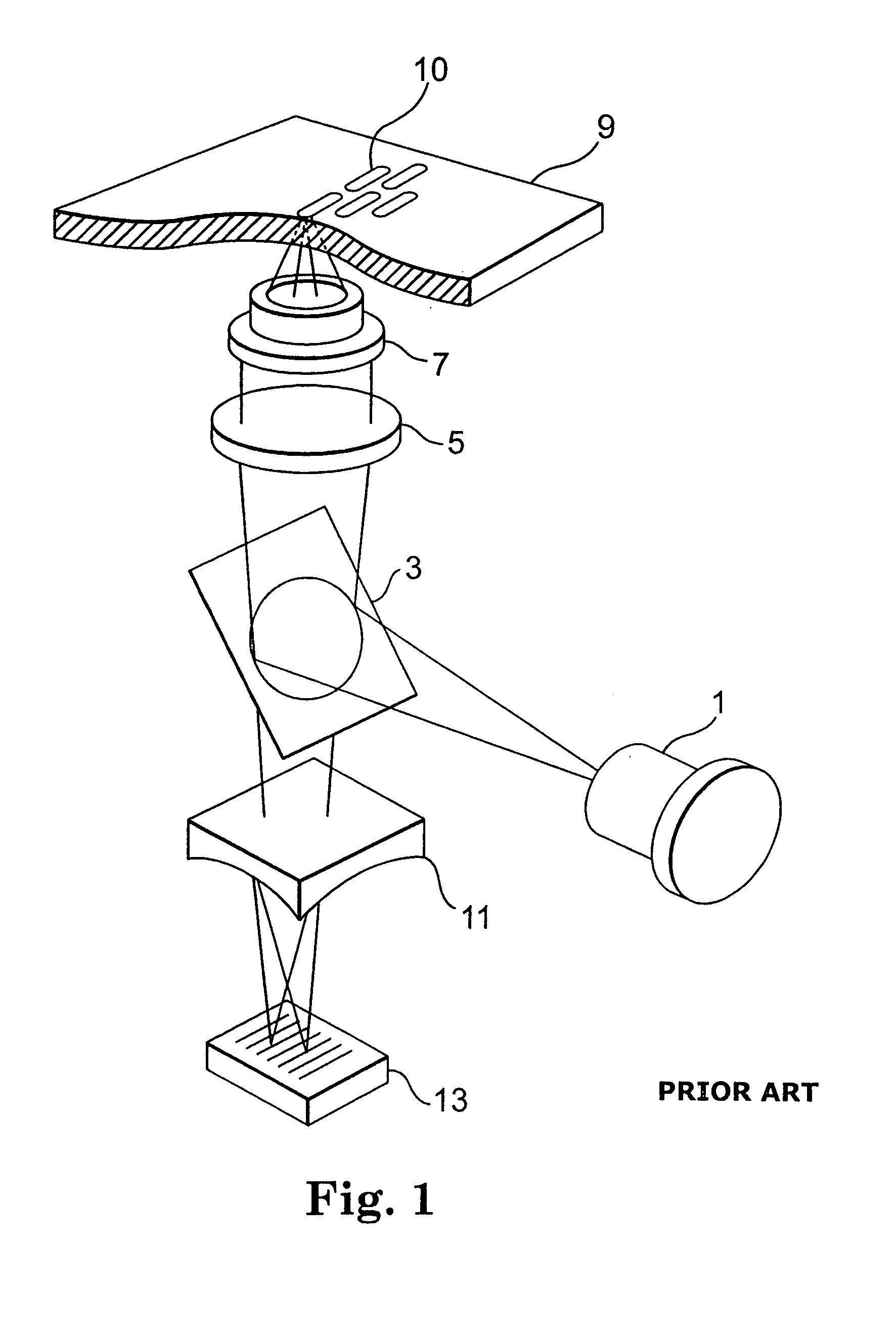
CROSS REFERENCE TO RELATED APPLICATIONS[0001]This application claims priority from U.S. Provisional Patent Application Ser. No. 60 / 426,722 filed Nov. 15, 2002.BACKGROUND OF THE INVENTION[0002]An example of an optical read / write system is shown in FIG. 1. It can be seen that a beam is created and emitted by a laser diode 1. The beam first encounters a beam splitter 3, which splits the beam into multiple beams and reflects these beams toward a collimator 5. The collimator 5 is a type of lens that is constructed and arranged to form a collimated beam. After the split beams pass through the collimator 5, they are parallel with each other and until they pass through an objective lens 7. The objective lens 7 bends the beams so that they all converge at a focal point, which is preferably at the surface or information layer of the media 9. The objective lens 7 may be mounted on a lens actuator that can adjust the distance between the lens and the media, which thereby controls focusing and t...

Claims


Application Information

Patent Timeline
Patent Type & Authority Patents(United States)
IPC IPC(8): G11B7/00G11B7/135
CPCG11B7/1392
Inventor RUSSELL, ROBERT G.STAHL, RONALD P.
Owner ALLIANCE STORAGE TECH
Learn More