
Field installable optical fiber connector

a technology installation processes, applied in the field of optical fiber connectors, can solve the problems of not being able to determine the respective lengths of the shorter optical fibers, not being able to customize the installation process, and not being able to meet the requirements of every application

Active Publication Date: 2007-04-17
CORNING OPTICAL COMM LLC
View PDF30 Cites 142 Cited by
  • Summary
  • Abstract
  • Description
  • Claims
  • Application Information

AI Technical Summary

Problems solved by technology

However, the factory installation of fiber optic connectors is not altogether satisfactory for every application.
In particular, the factory installation of fiber optic connectors does not customize the installation process to account for the myriad of design variations experienced in the field.
However, the respective lengths of the shorter optical fibers cannot generally be determined until the optical fibers are installed in the field.
Thus, in this instance, the requisite optical fiber connectors cannot be mounted to the fibers at the factory prior to installation of the optical fiber.
Still further, it is desirable in many instances to package and ship optical fiber prior to the installation of the fiber optic connectors since the fiber optic connectors generally have a greater diameter than the respective optical fiber, and may unnecessarily complicate the packaging and shipping of the optical fiber.
This may result in compressing together the abutting end faces of the optical fibers and potentially damaging the end faces.
In addition, inserting and latching the connector into the receiving receptacle may prove to be troublesome.
Finally, the Camlite® connector, as with other field installable connectors, does not include a feature for readily and visually determining that an acceptable splice has been made.

Method used


Image

  • Field installable optical fiber connector
  • Field installable optical fiber connector
  • Field installable optical fiber connector

Examples


Embodiment Construction

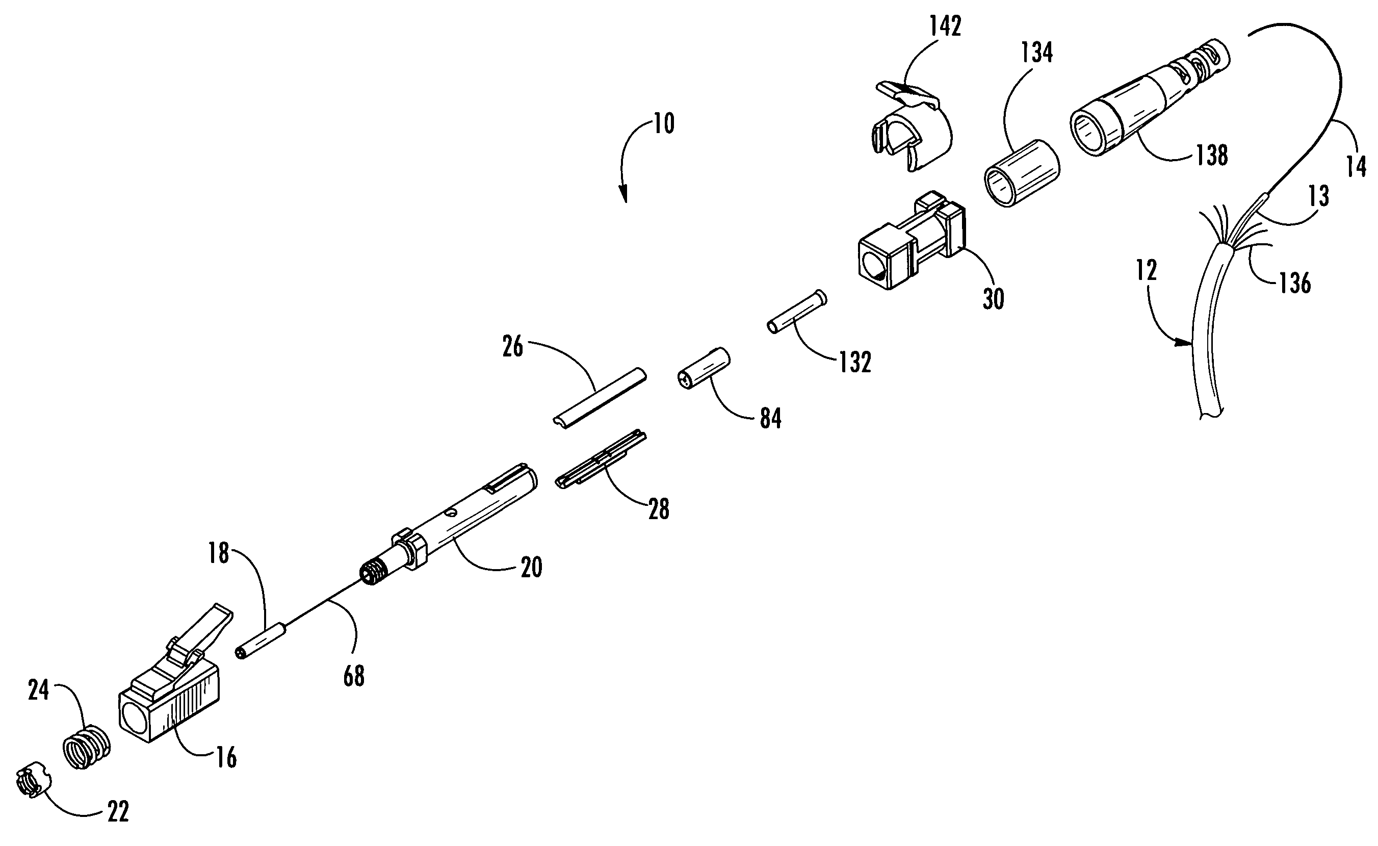
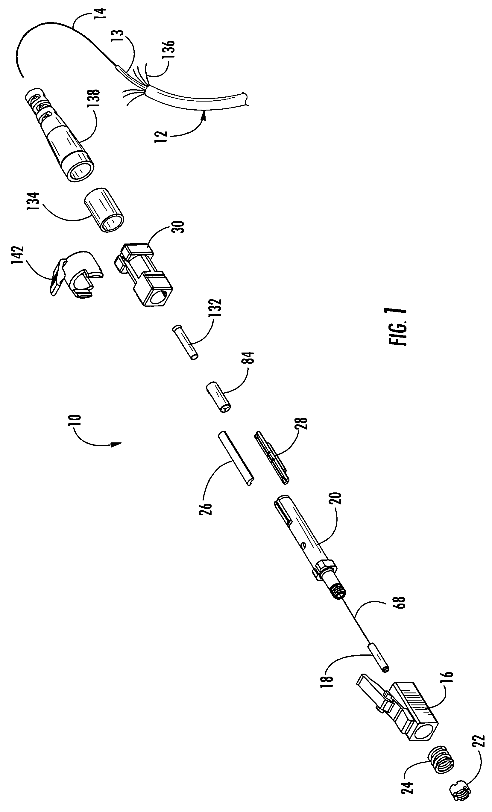
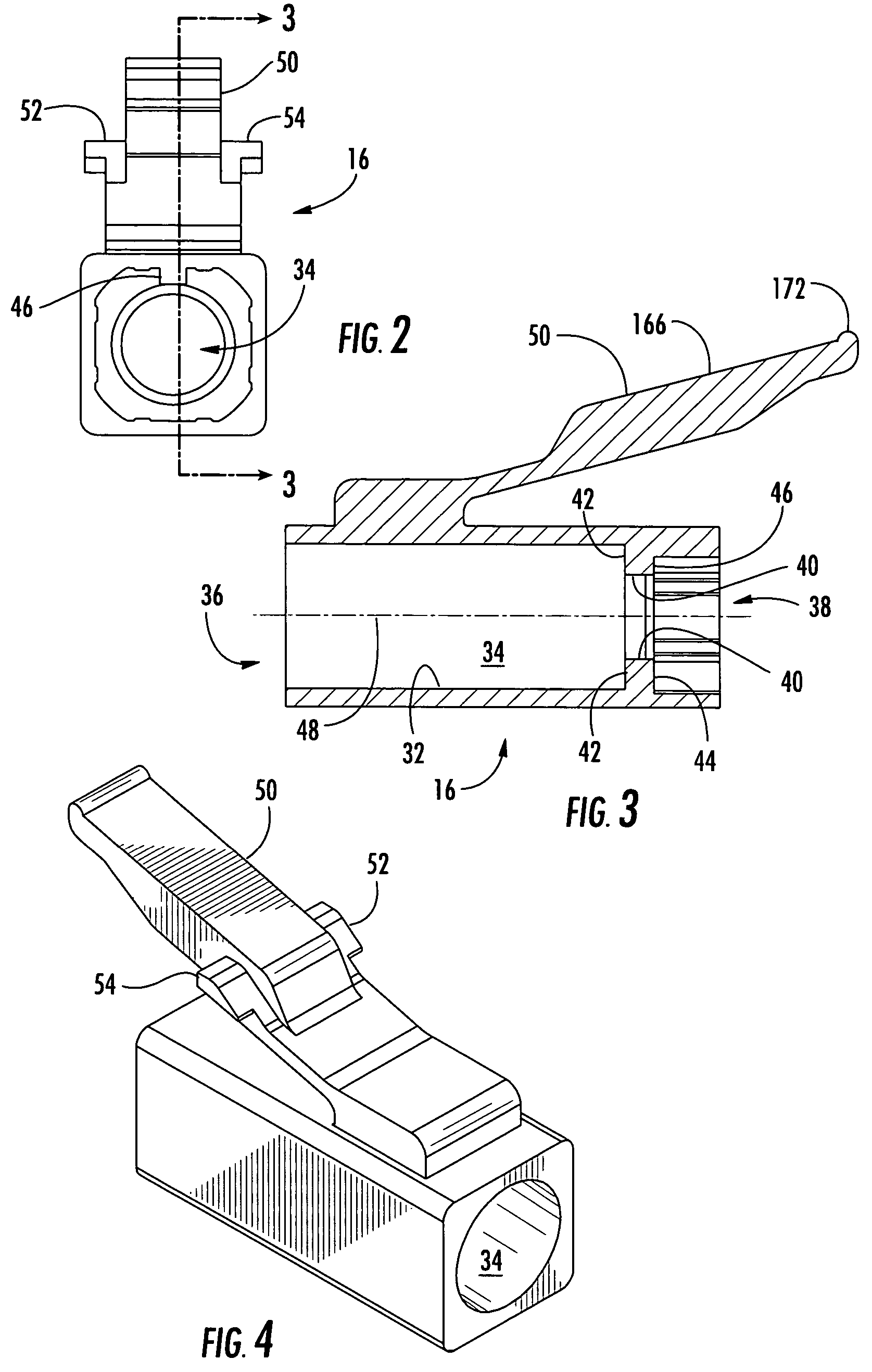
[0059]Detailed references will now be made to the drawings in which examples embodying this invention are shown. The drawings and detailed description provide a full and detailed written description of the invention, and of the manner and process of making and using it, so as to enable one skilled in the pertinent art to make and use it, as well as the best mode of carrying out the invention. However, the examples set forth in the drawings and detailed description are provided by way of explanation of the invention and not meant as a limitation of the invention. This invention thus includes any modifications and variations of the following examples as come within the scope of the appended claims and their equivalents.

[0060]The detailed description uses numerical and letter designations to refer to features in the drawings. Like or similar designations in the drawings and description have been used to refer to like or similar parts of the invention.

[0061]As embodied in FIG. 1, a fibe...


PUM


Abstract

A field installable fiber optic connector includes a housing and a ferrule holder inserted from the rearward end of the housing. A spring element inserted into the front of the housing and a spring element retainer attached to the ferrule holder bias the ferrule holder forward. An optical fiber stub is disposed between opposed splice members and a field fiber is inserted between the splice members and guided by a groove into abutment with the end of the optical fiber stub. A cam disposed about the ferrule holder is movable to facilitate insertion of the field fiber and to clamp the field fiber and the optical fiber stub between the splice members. In one embodiment, a trigger is coupled to the housing. The trigger is disposed about and slides relative to the ferrule holder, thereby biasing the housing forward relative to the ferrule holder to aid in latching the connector.

Description

CROSS REFERENCE TO RELATED APPLICATION[0001]This application is a continuation-in-part of U.S. patent application Ser. No. 10 / 808,057, filed on Mar. 24, 2004, now U.S. Pat. No. 7,104,702 which is assigned to the assignee of the present application.BACKGROUND OF THE INVENTION[0002]1. Field of the Invention[0003]The present invention relates generally to optical fiber connectors and more particularly to optical fiber connectors adapted for field installation.[0004]2. Technical Background[0005]Optical fibers are widely used in a variety of applications, including the telecommunications industry in which optical fibers are employed in a number of telephony and data transmission applications. Due, at least in part, to the extremely wide bandwidth and the low noise operation provided by optical fibers, the use of optical fibers and the variety of applications in which optical fibers are used are continuing to increase. For example, optical fibers no longer serve as merely a medium for lon...

Claims


Application Information

Patent Timeline
Patent Type & Authority Patents(United States)
IPC IPC(8): G02B6/36G02B6/38
CPCG02B6/3806G02B6/3821G02B6/3833G02B6/3846G02B6/3887G02B6/3893G02B6/3888
Inventor BARNES, BRANDON A.BILLMAN, BRAD S.MEEK, DAVID W.SEMMLER, SCOTT E.FORSBERG, JASON F.
Owner CORNING OPTICAL COMM LLC
Learn More