
Safety for a hand firearm

a hand firearm and safety technology, applied in the direction of safety arrangements, breech mechanisms, weapons components, etc., can solve the problems of increasing the trigger weight, no longer sufficient trigger rods, etc., and achieve the effect of ensuring safety and shortened trigger paths

Active Publication Date: 2007-04-17
T SWISS ARMS TECH
View PDF21 Cites 33 Cited by
  • Summary
  • Abstract
  • Description
  • Claims
  • Application Information

AI Technical Summary

Benefits of technology

This configuration ensures high safety against unintended firing even with a shortened trigger path while maintaining a low trigger weight, preventing accidental discharges due to vibrations or impacts.

Problems solved by technology

However, if the trigger path in such safety systems is to be shortened, there is the problem that the resulting smaller shifting of the trigger rod is no longer sufficient to move the safety element from the predetermined safety position into the released position.
Increasing the spring force on the safety element in the safety position would in turn increase the trigger weight, which could have a negative effect on the firing behavior.

Method used


Image

  • Safety for a hand firearm
  • Safety for a hand firearm
  • Safety for a hand firearm

Examples


Embodiment Construction

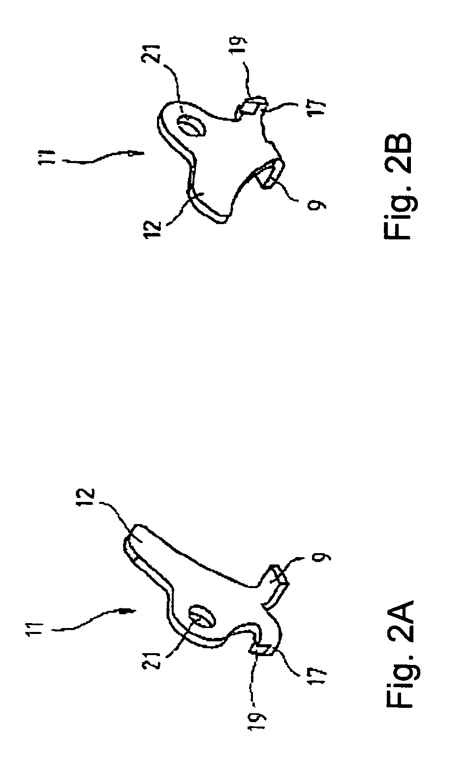
[0016]FIG. 1 shows a trigger 1, which is arranged in a not-shown handle, an insert, or another suitable part of a hand firearm so that it can rotate about a trigger pin 2. The front end of a trigger rod 3 is hinged to a part of the trigger 1 lying above the trigger pin 2 such that the trigger rod 3 is moved forward when the trigger 1 is activated. In the rear region of the trigger rod 3, on the bottom side there is a projection 4, which is bent inwards and which is used to activate a releasing lever, which is not shown here. The hammer 6 that can rotate about a hammer shaft 5 and that is biased by a hammer spring is released by the releasing lever for striking a firing pin 7. This function is known, so that the illustration of the releasing lever interacting with the projection 4, as well as other components not required for the description of the safety have been omitted for reasons of clarity.

[0017]In the rear region of the trigger rod 3, on its top side there is a tab 8, which pr...


PUM


Abstract

A safety for a hand firearm with a firing lever, a firing pin, a safety element allocated to the firing pin, a trigger rod that can be activated by a trigger, and a transmission element, which is coupled to the trigger rod and through which the safety element can be moved from a safety position for blocking the firing pin into a released position for releasing the firing pin. To guarantee a high degree of safety against undesired firing of a shot even for a small trigger path and low trigger weight, the transmission element contains a control element, through which the transmission element can be activated in a predetermined trigger position of the trigger by means of the firing lever for moving the safety element into the released position.

Description

BACKGROUND OF THE INVENTION[0001]1. Field of the Invention[0002]The invention pertains to a safety for a hand firearm.[0003]2. Prior Art[0004]Mechanical safeties for hand firearms are already known, in which a safety element interacting with the firing pin is activated by means of a transmission element coupled to the trigger rod. The transmission element transmits the motion of the trigger rod to the safety element such that the safety element is biased into a safety position, usually by a spring until a desired trigger point is reached. Then, the safety element is released by the rocking lever into a released position. However, if the trigger path in such safety systems is to be shortened, there is the problem that the resulting smaller shifting of the trigger rod is no longer sufficient to move the safety element from the predetermined safety position into the released position. The path provided between the safety position and the released position of the safety element should n...

Claims


Application Information

Patent Timeline
Patent Type & Authority Patents(United States)
IPC IPC(8): F41A17/72
CPCF41A17/72
Inventor THOMELE, ADRIANMETZGER, THOMAS
Owner T SWISS ARMS TECH
Learn More