
Lock mechanism, and external apparatus and image forming apparatus provided with the same

a technology of external apparatus and image forming apparatus, which is applied in mechanical apparatus, electrographic process, instruments, etc., can solve the problems of cumbersome coupling work of apparatuses, inability to easily separate apparatuses from each other, and poor working property

Active Publication Date: 2007-04-10
CANON KK
View PDF16 Cites 22 Cited by
  • Summary
  • Abstract
  • Description
  • Claims
  • Application Information

AI Technical Summary

Benefits of technology

The present invention is a lock mechanism for locking two apparatuses. It includes a lock member that can be moved between a locked position and an unlocked position. The lock member is restrained in the unlocked position by a restraining portion. When the two apparatuses are brought close to each other, the restraint of the lock member is released, and the lock member moves from the unlocked position to the locked position. This invention solves the problem of accidental unlocking when the two apparatuses are close to each other.

Problems solved by technology

Consequently, the work for coupling the apparatuses together has been cumbersome.
Also, when the apparatus main body is to be moved or the external apparatus is to be replaced with another one, it is necessary to release the mounting of the two apparatuses and space them apart from each other, but if the apparatuses are fixed by the screws or the like, the apparatuses cannot be easily detached from each other, and the working property has been bad.
H05-084762), there is the problem that when the two apparatuses are spaced apart from each other, the stopper contacts with the pin to thereby hamper the spacing apart of the two apparatuses.
In such a state, the timing at which the stopper being in the lock releasing position is moved away from the part for maintaining the lock released state to the lock position quickens, and the above-noted problem that the stopper contacts with the pin to thereby hamper the spacing apart of the two apparatuses becomes great.
Further, in a case where in order to lock the two apparatuses reliably, a plurality of stoppers for locking are provided and the plurality of stoppers are moved as a unit, the above-noted problem becomes more remarkable.

Method used


Image

  • Lock mechanism, and external apparatus and image forming apparatus provided with the same
  • Lock mechanism, and external apparatus and image forming apparatus provided with the same
  • Lock mechanism, and external apparatus and image forming apparatus provided with the same

Examples


Embodiment Construction

[0034]Some embodiments of the present invention will hereinafter be described with reference to the drawings.

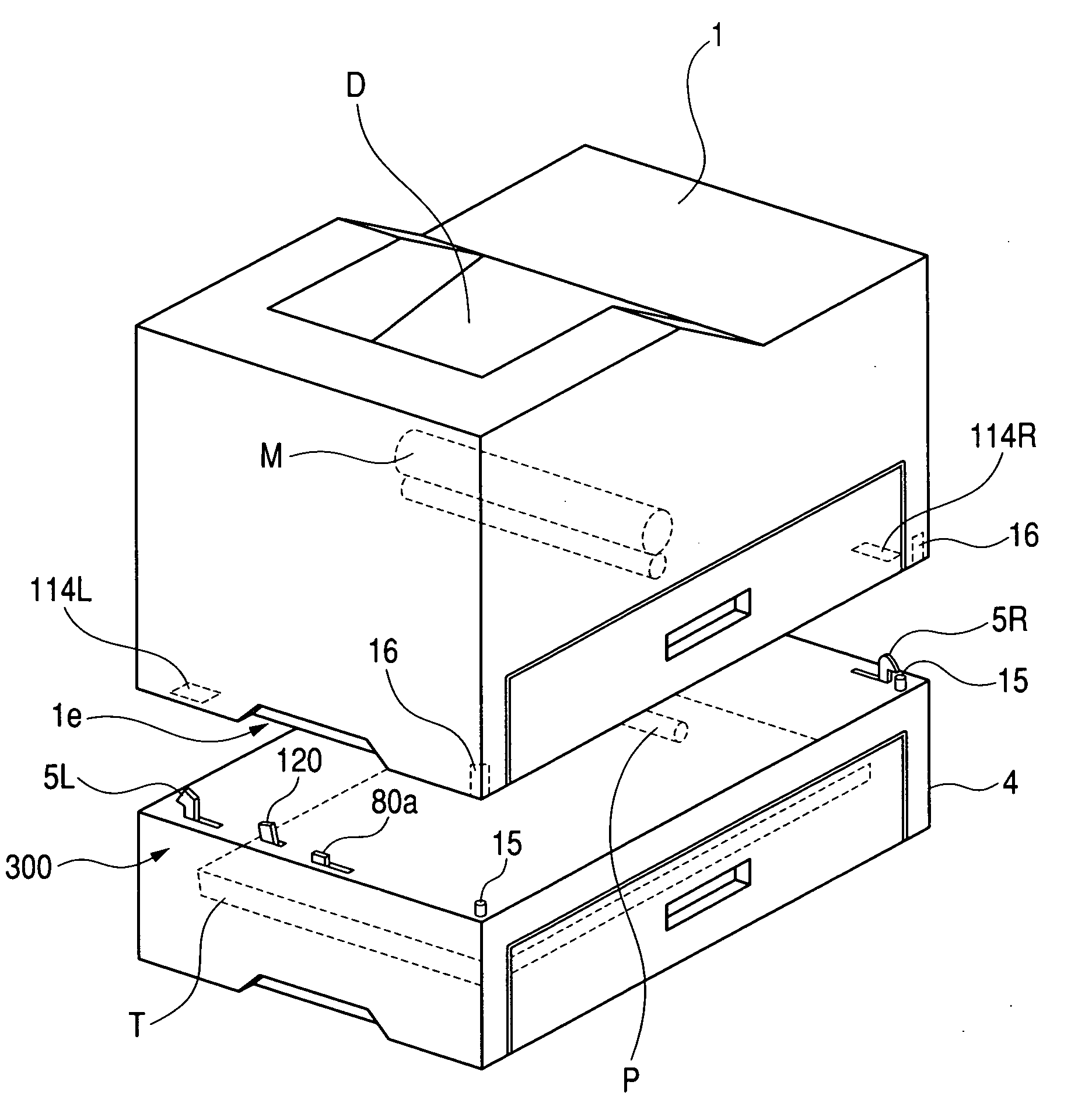
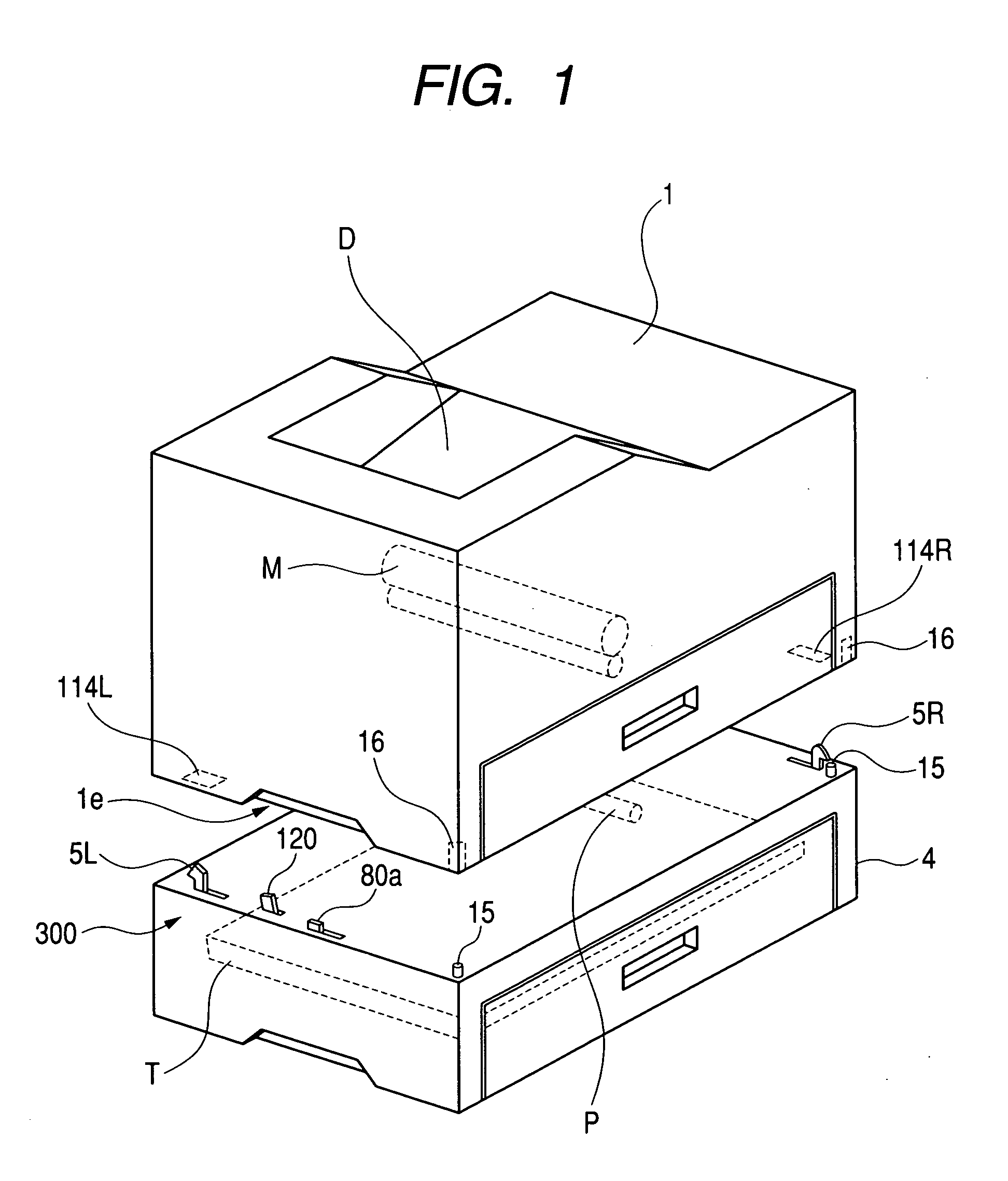
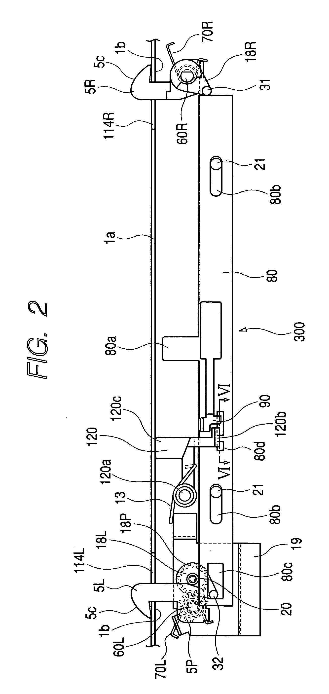
[0035]FIG. 1 is a perspective view showing the arrangement of a sheet feeding apparatus 4 as a second apparatus, an image forming apparatus main body as a first apparatus, and a lock mechanism 300 for locking the sheet feeding apparatus 4 and the image forming apparatus main body 1, FIG. 2 is a cross-sectional view showing the construction of the lock mechanism 300, and FIG. 3 is a perspective view of the lock mechanism 300, and all these figures show a state in which the sheet feeding apparatus 4 and the image forming apparatus main body 1 are locked by the lock mechanism 300.

[0036]As shown in FIG. 1, the sheet feeding apparatus 4 serving also as a supporting stand for the image forming apparatus main body 1 is disposed under the image forming apparatus main body 1. The sheet feeding apparatus 4 has a sheet feeding tray T for supporting thereon recording sheets on which imag...


PUM


Abstract

A lock mechanism is provided with a lock member moved between a locking position for locking a first apparatus and a second apparatus, and a non-locking position for not locking the first apparatus and the second apparatus, and a restraining portion for restraining the lock member in the non-locking position. With an operation of bringing the second apparatus and the first apparatus close to each other from a state in which the first apparatus and the second apparatus are spaced apart from each other, the restraint of the lock member by the restraining portion is released, and the lock member is moved from the non-locking position to the locking position.

Description

BACKGROUND OF THE INVENTION[0001]1. Field of the Invention[0002]The invention relates to a lock mechanism for locking a first apparatus and a second apparatus, an external apparatus provided with the same and connected to an image forming apparatus main body, and an image forming apparatus provided with the same.[0003]2. Related Background Art[0004]For example, there are many image forming apparatuses designed to permit the additional provision of a sheet feeding apparatus for making the sheet feeding capacity thereof large, an external discharging apparatus for increasing the discharged sheet stacking capacity, or an external apparatus' such as an original reading apparatus for increasing the function of the apparatus.[0005]These external apparatuses are usually installed below or above an image forming apparatus main body, and it is often the case that a plurality of external apparatuses are usable in piles.[0006]When these external apparatuses are connected to the image forming a...

Claims


Application Information

Patent Timeline
Patent Type & Authority Patents(United States)
IPC IPC(8): G03G15/00F16H53/02G03G21/16H04N1/00
CPCG03G15/6511G03G21/1647G03G2221/1654G03G2221/1696Y10T292/0917Y10T292/0936
Inventor UCHIDA, YASUHIRO
Owner CANON KK
Learn More