
Spar disconnect system

a disconnect system and disconnect technology, applied in the field of offshore platforms, can solve problems such as ssmb modules, and achieve the effect of providing structural strength

Active Publication Date: 2007-04-03
TECH FRANCE SA
View PDF9 Cites 45 Cited by
  • Summary
  • Abstract
  • Description
  • Claims
  • Application Information

AI Technical Summary

Benefits of technology

The present invention is a spar-type platform that can be moved and detached from a sub-sea mooring buoy to avoid environmental threats. The platform has an upper hull structure that supports topside facilities and equipment, and a lower hull structure that functions as a sub-sea mooring buoy. The two hull structures are connected by a detachable connection mechanism, allowing for easy disconnection and reconnection. The invention also includes a guiding structure for aligning the two hull structures and connecting the risers between them. The technical effects of the invention include improved safety and flexibility in responding to environmental threats, as well as more efficient and flexible operations.

Problems solved by technology

The weight of the mooring lines and risers, now unsupported by the buoyancy provided by the upper hull structure, causes the SSMB module to separate from the upper hull structure.

Method used


Image

  • Spar disconnect system
  • Spar disconnect system
  • Spar disconnect system

Examples


Embodiment Construction

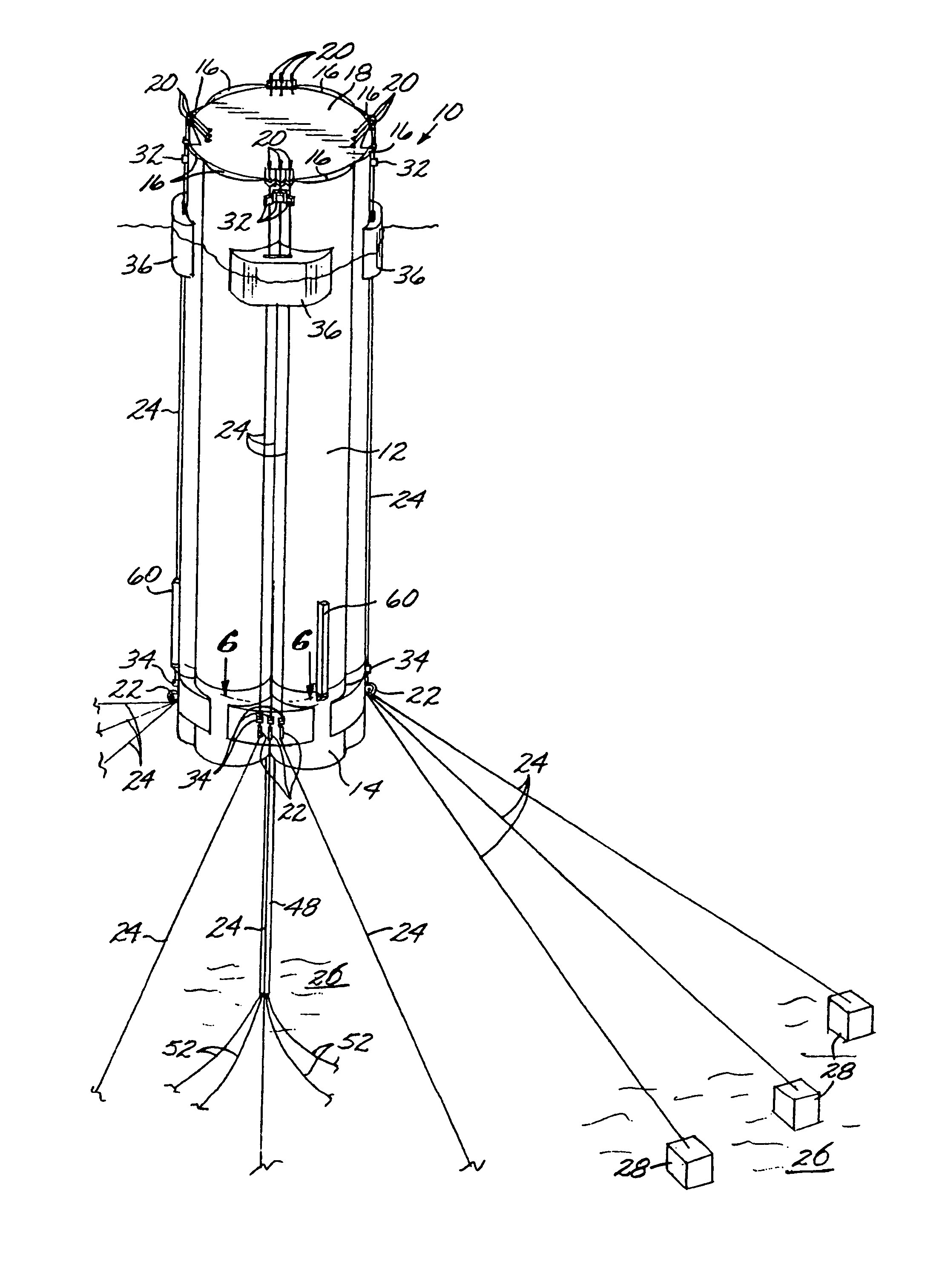
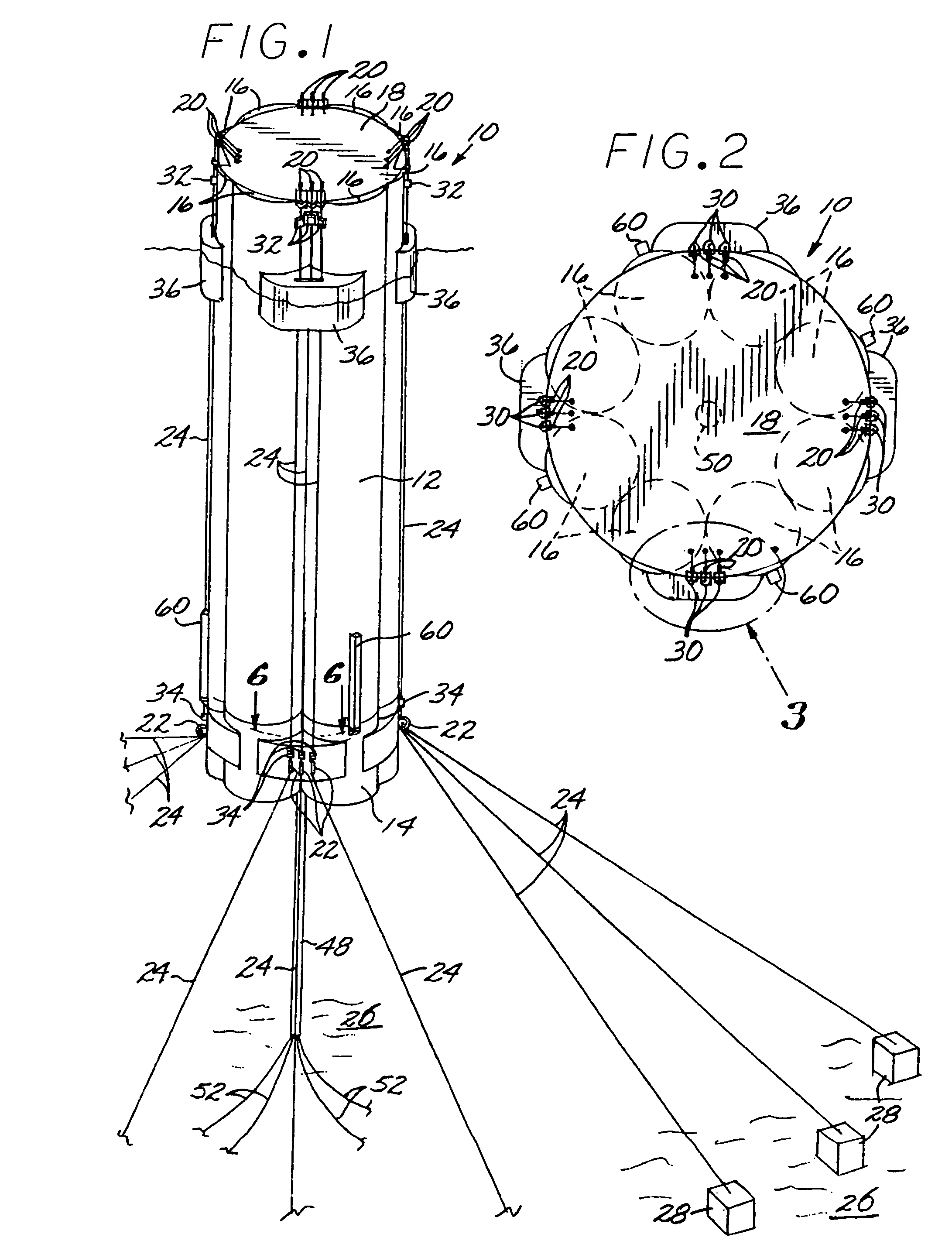
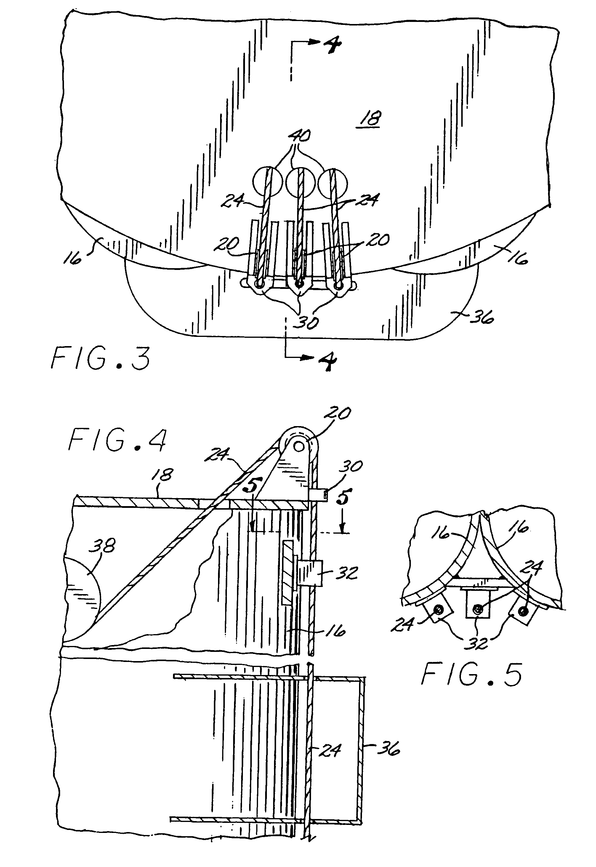
[0028]Referring now to the drawings, and particularly FIGS. 1, 2, and 9, a spar-type platform 10, in accordance with a preferred embodiment of the invention, includes an upper hull structure 12 and a buoyant lower section or module, configured as a sub-sea mooring buoy (SSMB) 14, wherein the upper hull structure 12 and the SSMB module 14 are detachably connected to each other so that the upper hull structure 12 can be removed from the SSMB module 14 and relocated, either by towing or under its own power. The SSMB module 14 can be subsequently retrieved and reconnected to the upper hull structure 12. The invention is described herein in the context of a cell spar, but it will be understood that it is easily adaptable for use with a so-called “classic” spar and with a truss spar.

[0029]The upper hull structure 10 comprises a plurality of interconnected elongate, hollow cells 16, each of which may be divided by a series of vertically-spaced, transverse bulkheads (not shown) into a plura...


PUM


Abstract

A spar-type offshore platform includes a buoyant upper hull structure supporting a deck and having lower end in which is received a buoyant lower mooring module. The upper hull structure is connected to the mooring module by connection lines. The upper hull structure is removed from the mooring module by disconnecting the connection lines from the upper hull structure while leaving the connection lines attached to the mooring module and while the mooring module remains moored to the seabed. The mooring module is lowered relative to the upper hull structure, allowing the latter to be moved away. The upper hull structure may be re-positioned over the mooring module, and the mooring module may be hauled upward into engagement with the lower end of the upper hull structure, so that the connection lines can be recovered and re-attached to the upper hull structure.

Description

CROSS-REFERENCE TO RELATED APPLICATION[0001]This application claims the benefit, under 35 U.S.C. §119(e), of co-pending provisional application No. 60 / 617,346, filed Oct. 8, 2004, the disclosure of which is incorporated herein by reference.FEDERALLY SPONSORED RESEARCH OR DEVELOPMENT[0002]Not ApplicableBACKGROUND OF THE INVENTION[0003]This application relates to offshore platforms for the exploration for, and production of, undersea petroleum deposits, and, in particular, to the various types of platforms generically known as spars, whether of the classic, truss, or cell spar variety. More specifically, the present invention relates to a spar-type platform, of the type having a buoyant upper hull structure and a lower buoyant section or module that supports the mooring and risers when the upper hull structure is detached, in which the lower section is constructed as a sub-sea mooring buoy (SSMB), wherein the upper hull section is detachably connected to the lower (SSMB) section.[0004...

Claims


Application Information

Patent Timeline
Patent Type & Authority Patents(United States)
IPC IPC(8): B63B35/44
CPCB63B21/50B63B35/44B63B35/4413B63B2021/505B63B2035/442
Inventor MURRAY, JOHN
Owner TECH FRANCE SA
Learn More