Eureka AIR delivers breakthrough ideas for toughest innovation challenges, trusted by R&D personnel around the world.

Contraction type actuator

a technology of actuators and actuators, applied in the direction of generators/motors, machine/engines, device details, etc., can solve the problems of weaker bias magnetic field in the vicinity of the center in the axial direction, inability to efficiently apply the bias magnetic field to the magnetostrictive rod, and varied strength of the applied bias magnetic field, etc., to achieve efficient and evenly apply the bias magnetic field, small and simple structure, and large contraction amount

Inactive Publication Date: 2007-03-27
TDK CORPARATION
View PDF13 Cites 7 Cited by
  • Summary
  • Abstract
  • Description
  • Claims
  • Application Information

AI Technical Summary

Benefits of technology

[0009]To solve such problems, an object of the present invention is to provide a contraction type actuator which can efficiently and evenly apply a bias magnetic field to a magnetostrictive rod to obtain a large contraction amount, while having a small and simple structure.

Problems solved by technology

Thus, there was a problem that the bias magnetic field could not be efficiently applied to the magnetostrictive rod.
As a result, the strength of the bias magnetic field in the vicinity of the center in the axial direction is weaker than those in the vicinity of both ends in the axial direction.
Thus, there was a problem that the strength of the applied bias magnetic field varied in accordance with the axial position of the magnetostrictive rod.
Furthermore, such problems became obvious with increasing the length of an axis of the magnetostrictive rod to increase the contraction amount.

Method used


Image

  • Contraction type actuator
  • Contraction type actuator
  • Contraction type actuator

Examples


Embodiment Construction

[0026]Exemplary embodiments of the present invention will be hereinafter described with reference to the drawings.

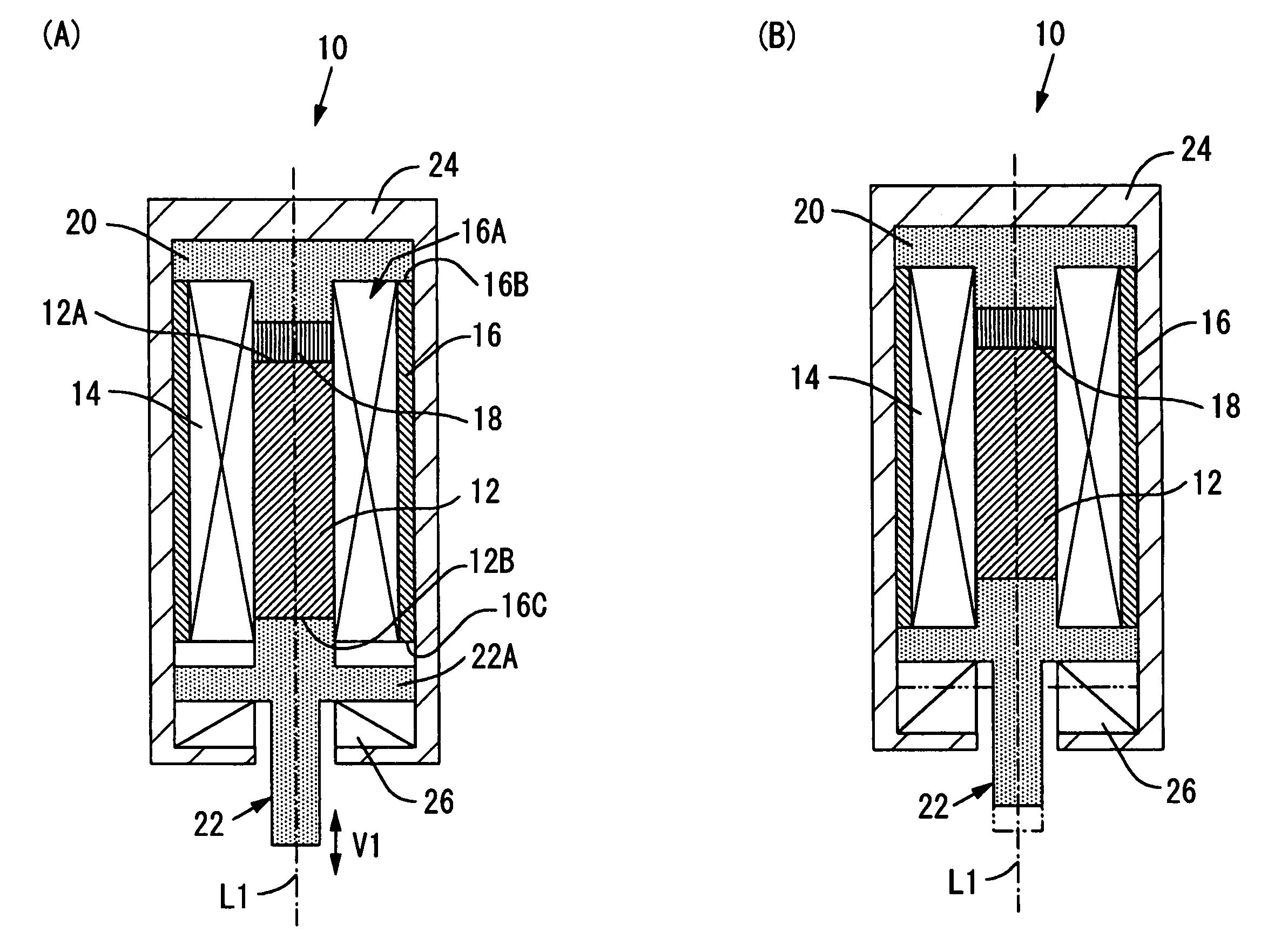
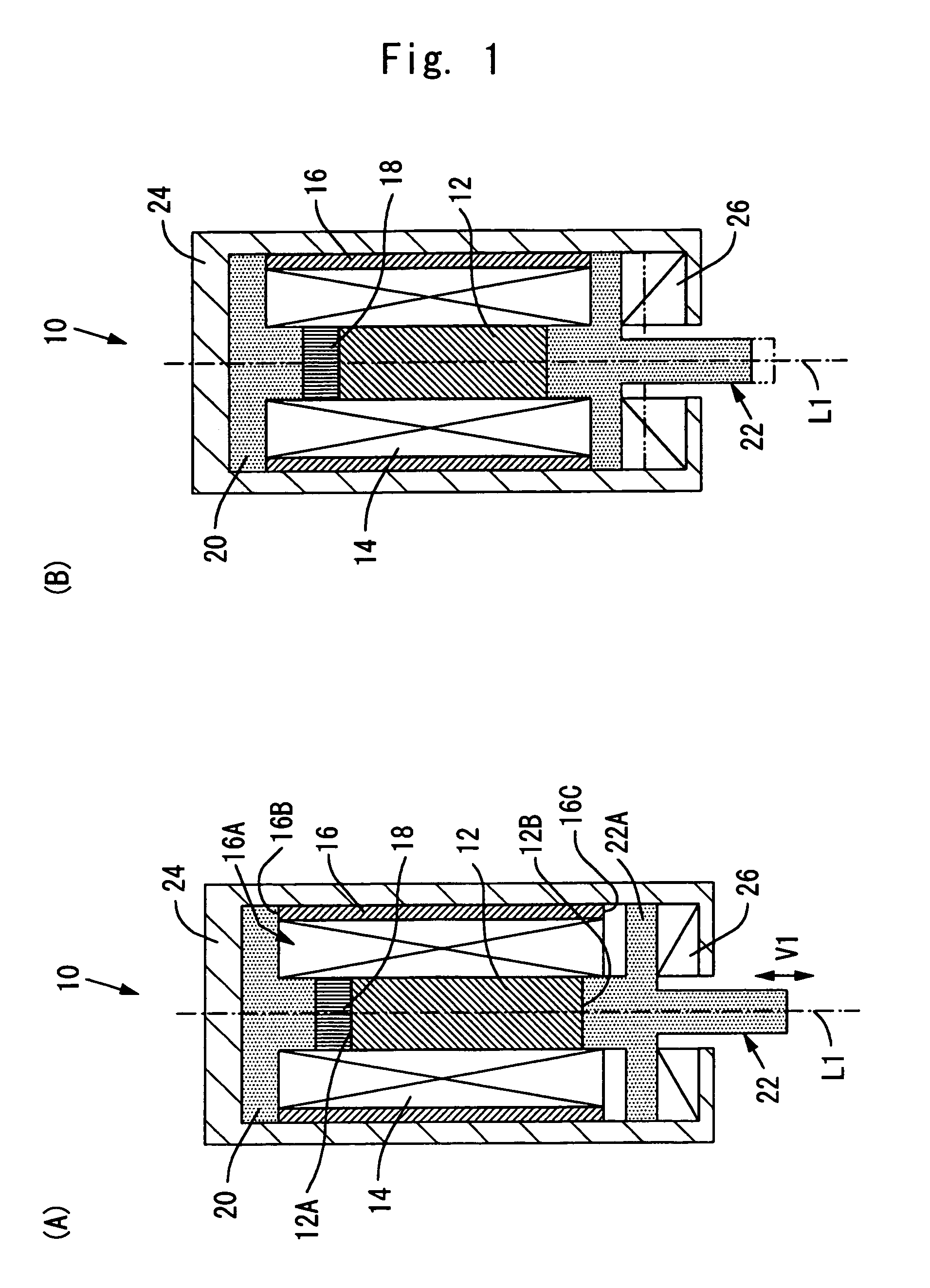
[0027]FIG. 1 schematically shows side sections of a contraction type actuator (hereinafter simply called actuator) 10 according to an exemplary embodiment of the present invention. FIGS. 1A and 1B show states in which a magnetostrictive rod 12 of the contraction type actuator 10 expands and contracts, respectively.

[0028]This actuator 10 comprises a magnetostrictive rod 12, a magnet coil 14, first and second bias magnets 16 and 18, a magnetic yoke 20, and a transmission rod 22. They are contained in a main body case 24 in an approximately cylindrical shape. In this actuator 10, the magnetostrictive rod 12 can expand and contract in a V1 direction of the drawing by controlling the strength of a magnetic field applied by the magnet coil 14. “Contraction operation” in which the magnetostrictive rod 12 is brought from an expansion state shown in FIG. 1A into a contraction sta...


PUM


Abstract

A contraction type actuator 10 is provided which can efficiently and evenly apply a bias magnetic field to a magnetostrictive rod to obtain a large contraction amount, while having a small and simple structure.In the contraction type actuator 10, a giant magnetostrictive rod 12 flexibly expands and contracts by controlling the strength of a magnetic field applied by a magnet coil 14. A bias magnet comprises a first bias magnet 16 and a second bias magnet 18. The fist bias magnet 16 in an approximately cylindrical shape is coaxially disposed around the giant magnetostrictive rod 12. The second bias magnet 18 is disposed in the inner space 16A of the first bias magnet 16, and is polarized in the direction of drawing a part of a magnetic field generated by the first bias magnet 16 into the inner space 16A.

Description

BACKGROUND[0001]1. Technical Field[0002]The present invention relates to a contraction type actuator in which a magnetostrictive rod contracts in an axial direction by applying a magnetic field to the magnetostrictive rod. In particular, the present invention relates to a contraction type actuator which can efficiently and evenly apply a bias magnetic field to the magnetostrictive rod to obtain a large contraction amount, while having a small and simple structure.[0003]2. Background Art[0004]Conventionally, an actuator which utilizes the characteristic of a magnetostrictive element in which applying a magnetic field distorts a magnetic material is widely known. In this magnetostrictive element, a magnetostrictive member can expand and contract by controlling the strength of a magnetic field applied to the magnetostrictive member. The actuator using such a magnetostrictive element is widely applied to the field of precision equipment, a fuel injection valve of an automobile, and the ...

Claims


Application Information

Patent Timeline
Patent Type & Authority Patents(United States)
IPC IPC(8): H01L41/06F02M51/00H01L41/12H02N2/04
CPCH01L41/12H10N35/00
Inventor MORI, TERUO
Owner TDK CORPARATION
Why Eureka
Eureka Blog
Learn More