
Hollowing system

Active Publication Date: 2007-03-20
TSDR
View PDF14 Cites 7 Cited by
  • Summary
  • Abstract
  • Description
  • Claims
  • Application Information

AI Technical Summary

Problems solved by technology

This process is difficult for several reasons.
First, there are forces placed on the tool that tend to push the tip of the tool downward as well as rotate the tool around its long axis.

Method used


Image

  • Hollowing system
  • Hollowing system
  • Hollowing system

Examples


Embodiment Construction

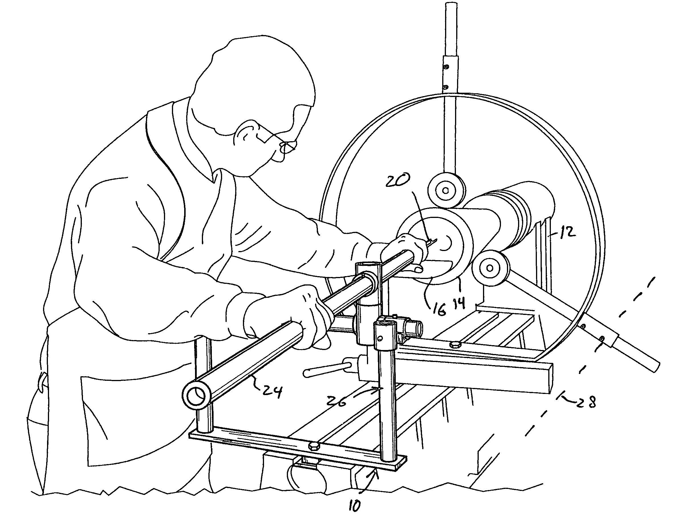
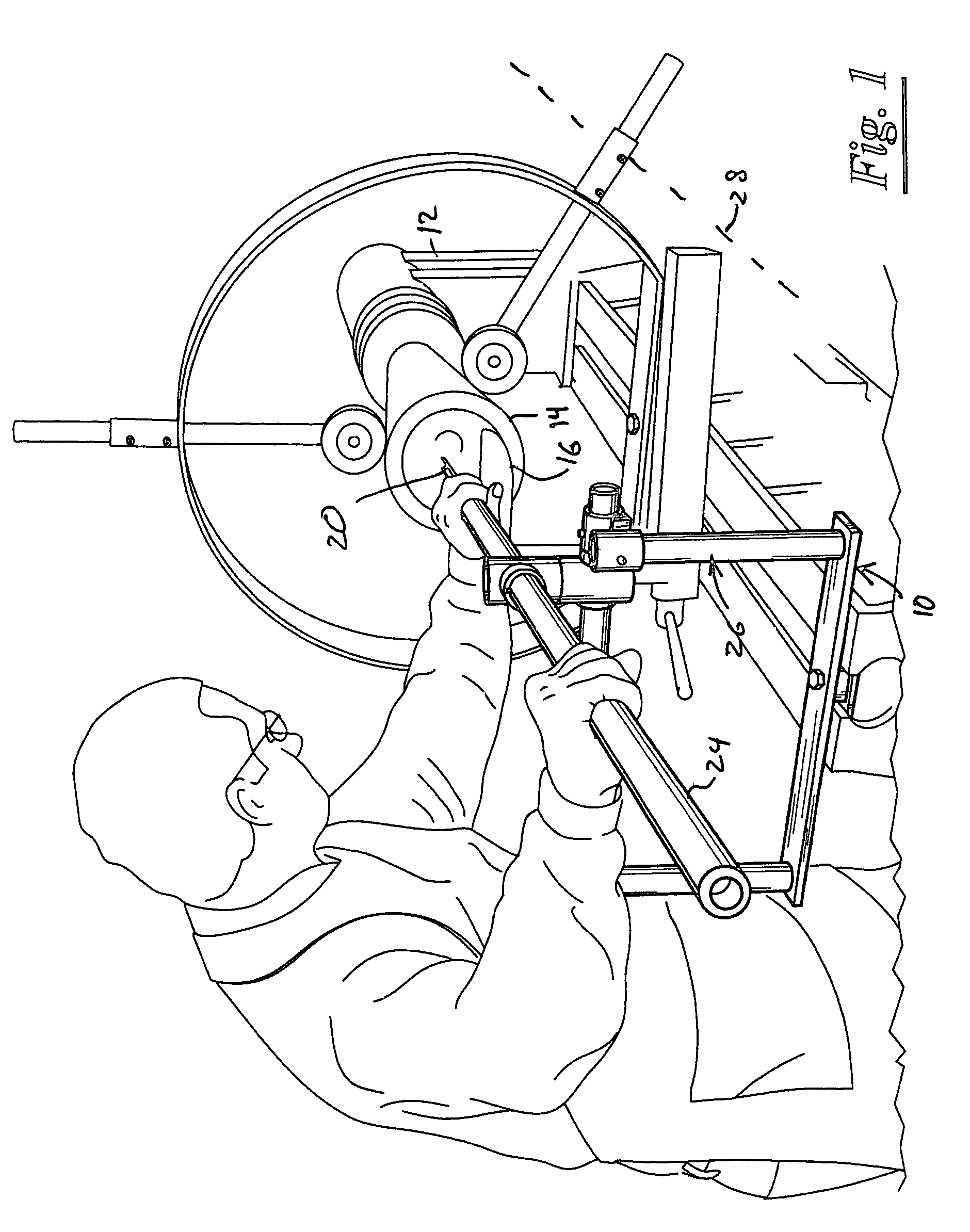
[0010]Referring now to the drawings, and more particularly to FIG. 1, shown therein and designated by a reference numeral 10, is a hollowing system constructed in accordance with the present invention. The hollowing system 10 is mounted either on or adjacent to a lathe 12. A workpiece 14, such as a log, is mounted to and supported by the lathe 12 in a well-known manner. The lathe 12 also includes a tool rest 16, which is positioned generally between the workpiece 14 and the hollowing system 10 to support a tool 20 used for removing wood or other material from the workpiece 14.

[0011]The tool 20 can be any type of cutter for removing wood or other materials from the workpiece 14. For example, the tool 20 can be a cutting tool such as a gouge, parting tool, skew chisel, round nose chisel, spear point chisel or scraper.

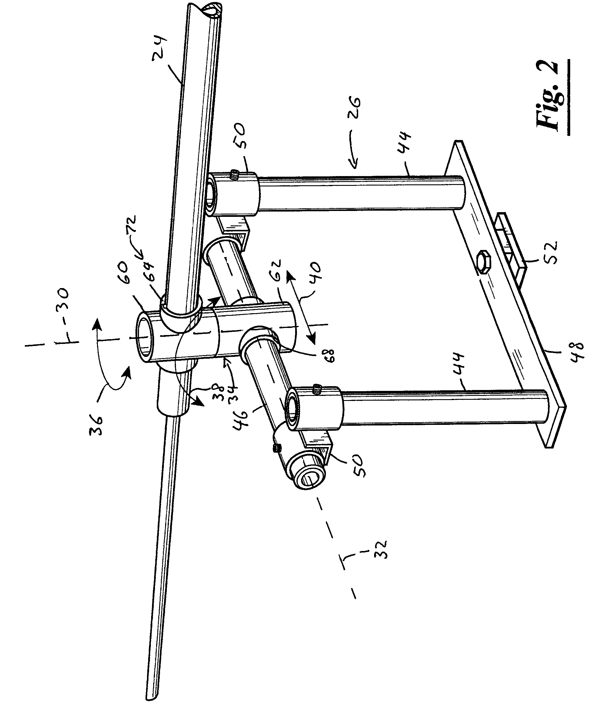
[0012]The hollowing system 10 is provided with a boring member 24, and a stabilization assembly 26. The boring member 24 supports the tool 20. The boring member 24 can be...


PUM

PropertyMeasurementUnit
Shapeaaaaaaaaaa

Abstract

A hollowing system for a lathe having a tool rest. The hollowing system comprises a boring member, and a stabilization assembly. The boring member is adapted to support a tool such that at least one of the boring member and the tool extend past and engage the tool rest. The stabilization assembly is mountable adjacent to the lathe. The stabilization assembly supports the boring member such that the boring member extends generally parallel to a longitudinal axis of the lathe. The stabilization assembly has a vertical axis and a horizontal axis. The stabilization assembly is adapted to prevent downward movement of the tool when the stabilization assembly is mounted adjacent to the lathe and the tool is positioned on the tool rest. The stabilization assembly is provided with an articulation assembly. The articulation assembly supports the boring member and permits horizontal movement of the boring member about the vertical axis, while also permitting lateral movement of the boring member in a horizontal direction.

Description

CROSS REFERENCE TO RELATED APPLICATIONS[0001]The present patent application claims priority to the provisional patent application filed on Mar. 14, 2003, U.S. Ser. No. 60 / 455,099, the entire content of which is hereby incorporated herein by reference.STATEMENT REGARDING FEDERALLY SPONSORED RESEARCH AND DEVELOPMENT[0002]Not Applicable.BACKGROUND OF THE INVENTION[0003]The present invention relates to an aid to be used by a wood turner to ease the process of creating hollowed vessels on a wood turning lathe. Wood turning lathes have been used for creating hollowed vessels for many years. Typically, a wood turner mounts a log or other medium onto a lathe and then uses a handheld cutting tool to remove the solid wood from inside the log while leaving an outer rim that forms the walls of the vessel.[0004]Usually, a tool rest is placed next to the endgrain of the log and the handheld tool is advanced into the end grain of the log to hollow the wood. This process is difficult for several re...

Claims


Application Information

Patent Timeline
IPC IPC(8): B27C7/06B23B3/02B23B3/00
CPCB27C7/06Y10T82/10Y10T82/2585
Inventor CLARK, KEITH
Owner TSDR
Learn More