Medical instrument holding device
a technology for holding devices and medical instruments, applied in the field of medical instruments holding devices, can solve the problems of degrading operability, unbalanced structural parts during movement, and the operator must hold the medical instruments for a long time, and achieve the effect of reducing the amount of load applied and improving operability
- Summary
- Abstract
- Description
- Claims
- Application Information
AI Technical Summary
Benefits of technology
Problems solved by technology
Method used
Image
Examples
first embodiment
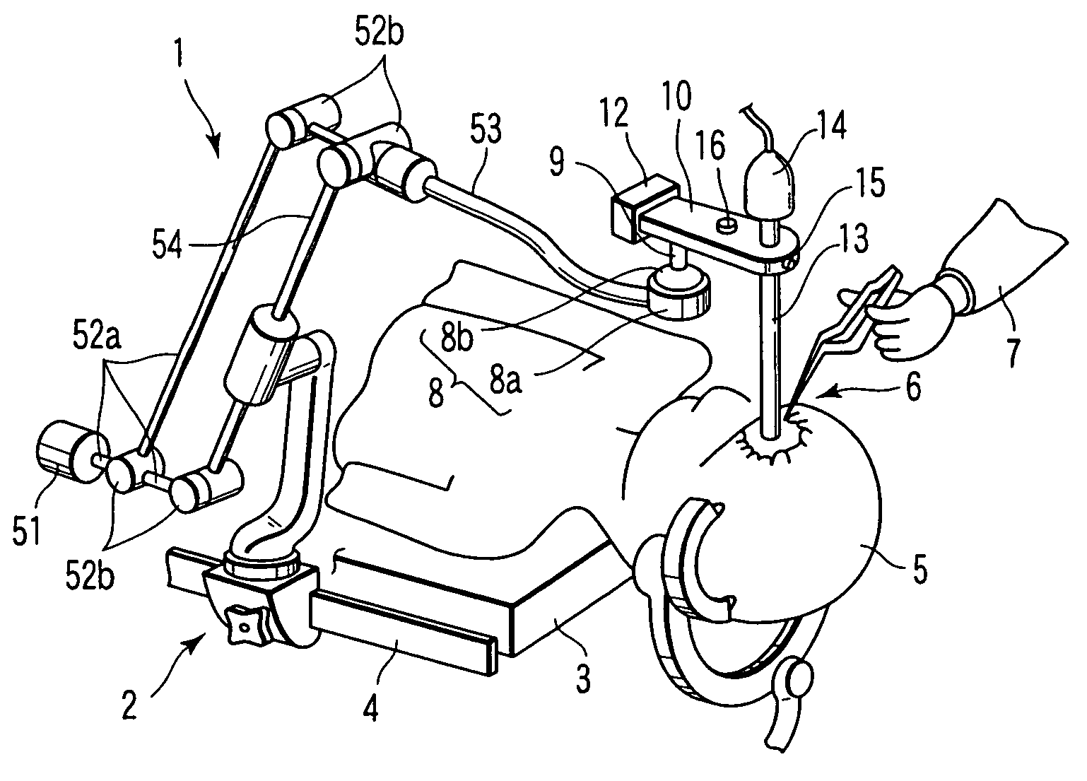
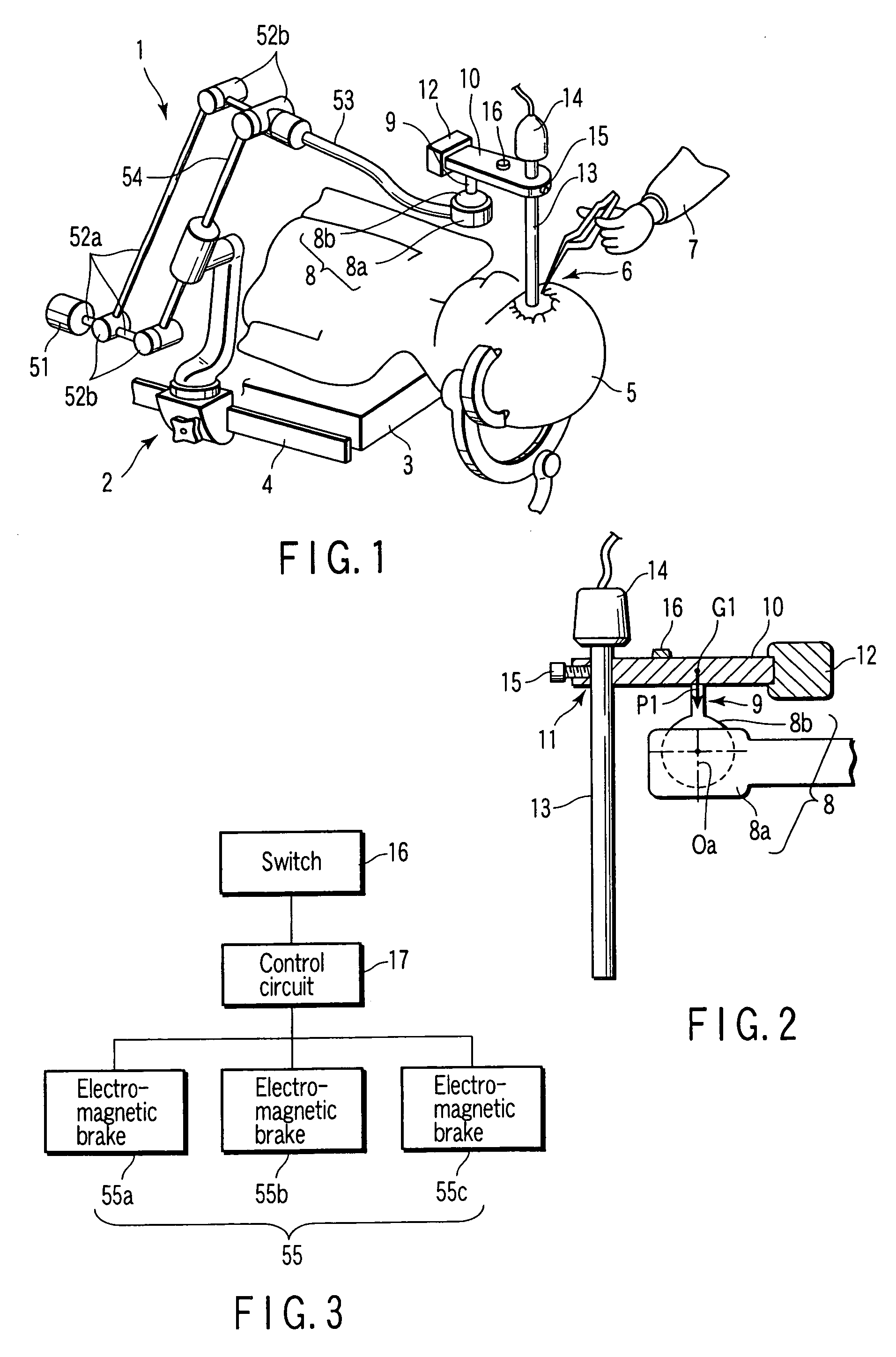
[0044]The function in the first embodiment will be explained hereafter.
[0045]In general, the surgical operation starts from the surface of a patient and opens a lumen 6 of the body, whose direction is substantially in vertical direction. The endoscope 13 is inserted with its insertion portion into the lumen 6 and arranged in the proximity of an operation site. An operator 7 observes through the endoscope 13 images at the operation site produced on a monitor (not shown) by means of the camera 14. In order to change the observation field of view of the endoscope 13, the operator 7 grasps the grasping portion 10 and pushes the switch 16 to release the fixed condition of the electromagnetic brakes 55a to 55c arranged at the respective moving parts through the control circuit 17 at a time. While a plurality of brakes are released at a time by an operation of the switch in the embodiment, it will be apparent that a plurality of switches may be provided to release individual brakes separat...
second embodiment
[0052]The medical instrument holding device of the invention will be explained thereafter.
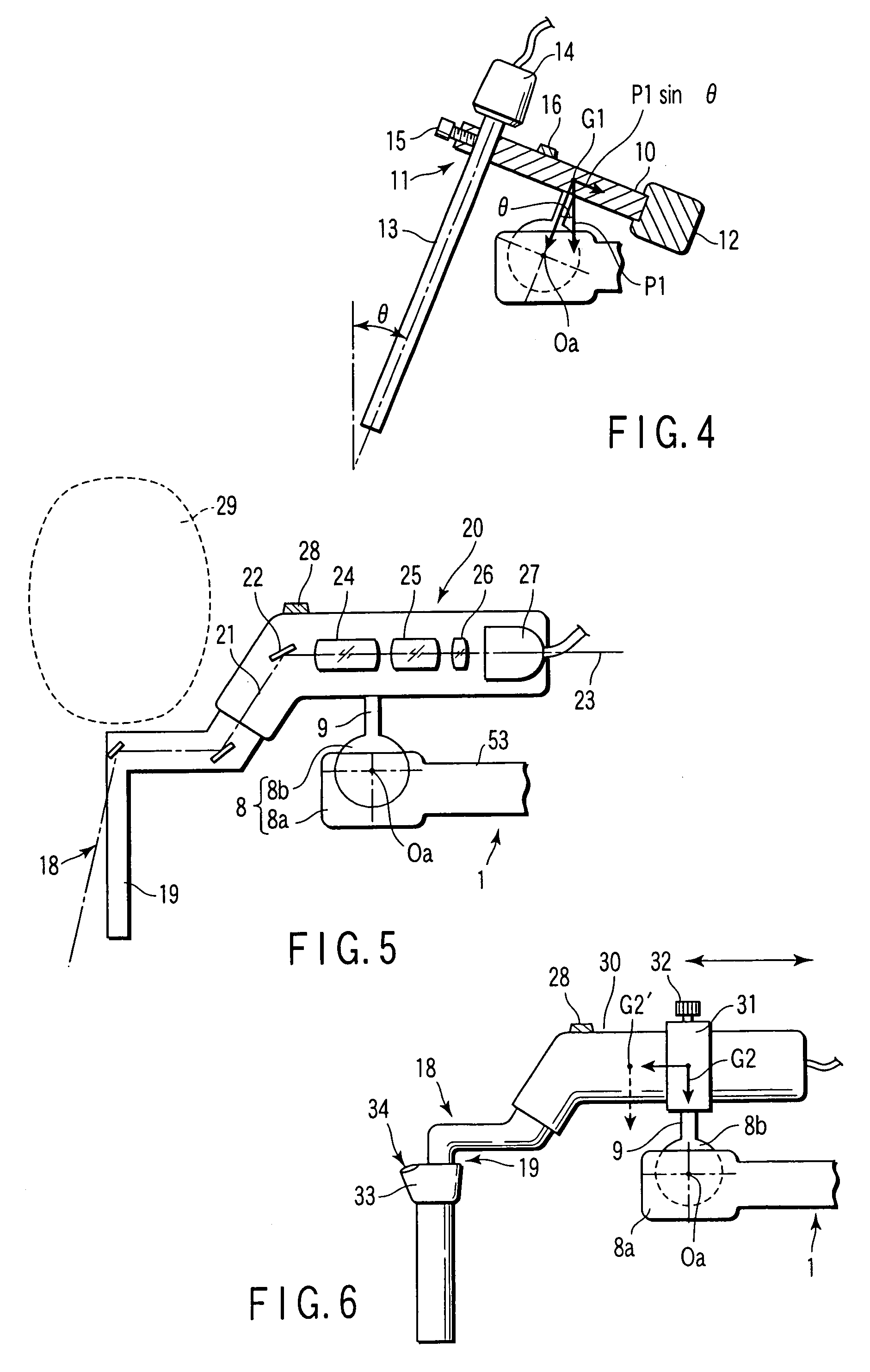
[0053]FIG. 5 illustrates in cross-section a grasping portion including an endoscope of the holding device.
[0054]The second embodiment has a construction equivalent to those of the parallelogram link mechanism (consisting of the connecting arm, the link arms, the articulations and the counter weight) connected to the acceptant arm in the first embodiment. In the second embodiment, a connecting arm 54 is supported by a connecting portion which is provided with a connecting arm and a support arm pivotally movable. Such a construction is applicable to the mechanism including the braking portions (pushing levers) by pushing levers as shown in FIG. 6 in Jpn. Pat. Appln. KOKAI Publication No. 2001-258903 mentioned above. In the articulations, moreover, electro-magnetic brakes functioning as braking means are provided.
[0055]Although in the first embodiment a medical instrument such as an endoscope is d...
third embodiment
[0062]The medical instrument holding device of the third embodiment according to the invention will be explained hereinafter.
[0063]FIG. 6 illustrates in section a grasping portion including an endoscope in the medical instrument holding device of the third embodiment. In the third embodiment, the grasping portion and the insertion shaft in the second embodiment are modified. Other than these features are substantially similar to those of the first and second embodiments, and components similar to those are identified by identical reference numerals and will not be described in further detail.
[0064]The grasping portion 30 is fitted in a ring member 31 and fixed thereto by a set screw 32. By loosening the set screw 32, the grasping portion 30 is moved slidably in the directions shown by an orienting arrow in the drawing. The ring member 31 is provided at its lower portion with a ball joint element 8b by means of a shaft 9. Mounted on the end of the grasping portion 30 is an endoscope ...
PUM
 Abstract
Description
Claims
Application Information
 - R&D
- Intellectual Property
- Life Sciences
- Materials
- Tech Scout
- Unparalleled Data Quality
- Higher Quality Content
- 60% Fewer Hallucinations
Browse by: Latest US Patents, China's latest patents, Technical Efficacy Thesaurus, Application Domain, Technology Topic, Popular Technical Reports.
© 2025 PatSnap. All rights reserved.Legal|Privacy policy|Modern Slavery Act Transparency Statement|Sitemap|About US| Contact US: help@patsnap.com


