
Tarp connector

a technology of connectors and connectors, applied in the field of accessories, can solve the problems of reducing the service life of tarps, so as to prevent accidental loosening of connectors and prevent tears from propagating

Inactive Publication Date: 2007-03-13
NEVADA NORTH COAST LIMTIED
View PDF7 Cites 26 Cited by
  • Summary
  • Abstract
  • Description
  • Claims
  • Application Information

AI Technical Summary

Benefits of technology

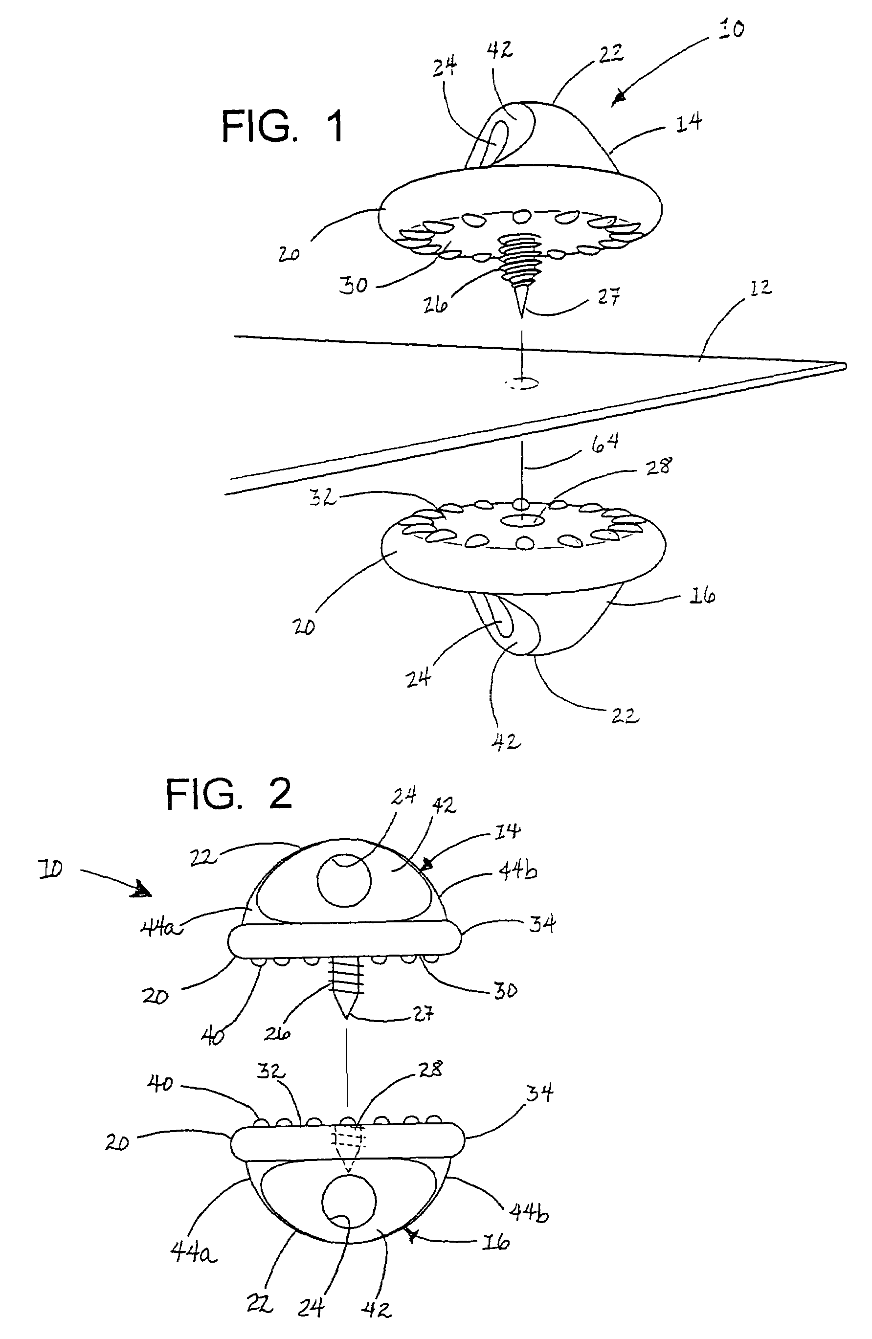
[0012]Each of the bearing faces on the connector members may comprise a plurality of raised protuberances for frictionally engaging material of the tarp so as to prevent accidental loosening of the connector members. The protuberances may have substantially rounded contours so as to avoid damaging of the material of the tarp that is engaged thereby. The raised protuberances may comprise a plurality of elongate, substantially oval protuberances arranged radially about the screw and socket portions of the connector members. The bearing faces may further comprise a raised, substantially flat-surfaced clamping ring formed around the screw and socket portions, respectively, for clamping the tarp around the opening formed by the screw portion so as to prevent tears from propagating therefrom.
[0013]Each of the bearing faces of the connector members may be substantially circular so as to evenly distribute loads into the material of the tarp that is engaged thereby. Each of the base portions may further comprise a radiused rim extending about a perimeter of the circular bearing face for compressively engaging material of the tarp so as to avoid the damage thereto. The radiused rim may comprise a rounded lip having a smoothly contoured radius that extends away from the plane of the flat bearing face to an arc of about 90° or greater.
[0016]The screw portion of the male connector member may comprise a tapered thread portion for gradually spreading material of the tarp so as to minimize damage to the material, as the material is penetrated by the screw portion. The screw portion may further comprise a straight-sided thread portion for engaging a corresponding straight-sided thread portion in the socket portion of the female connector member. The screw portion of the male connector member and the socket portion of the female connector member may be configured to form an interference fit when tightened together.

Problems solved by technology

However, these provide only a limited number of attachment points, and at locations that are rarely optimal for any particular situation.
The grommets also tend to tear out of the edges and corners of the material, rendering the tarp largely useless unless a substitute can be made.
Although some such prior devices have enjoyed varying degrees of success, they have also exhibited a number of deficiencies.
Firstly, all of the devices that rely on gripping the material in jaws and like structures are subject to slipping off when subjected to a load.
Many are limited by their design to exerting force in a direction generally parallel to the plane of the tarp, e.g., for gripping / pulling at the edge of the tarp, and are consequently unsuitable for use in central areas of the tarp.
Some, notably those using a ring-and-plug design, are also cumbersome and difficult to use.
Moreover, the gripping, pinching, and holding actions generated by these devices tend to both damage and unevenly load the fabric of the tarps, causing frequent rips and tears.

Method used


Image

  • Tarp connector
  • Tarp connector
  • Tarp connector

Examples


Embodiment Construction

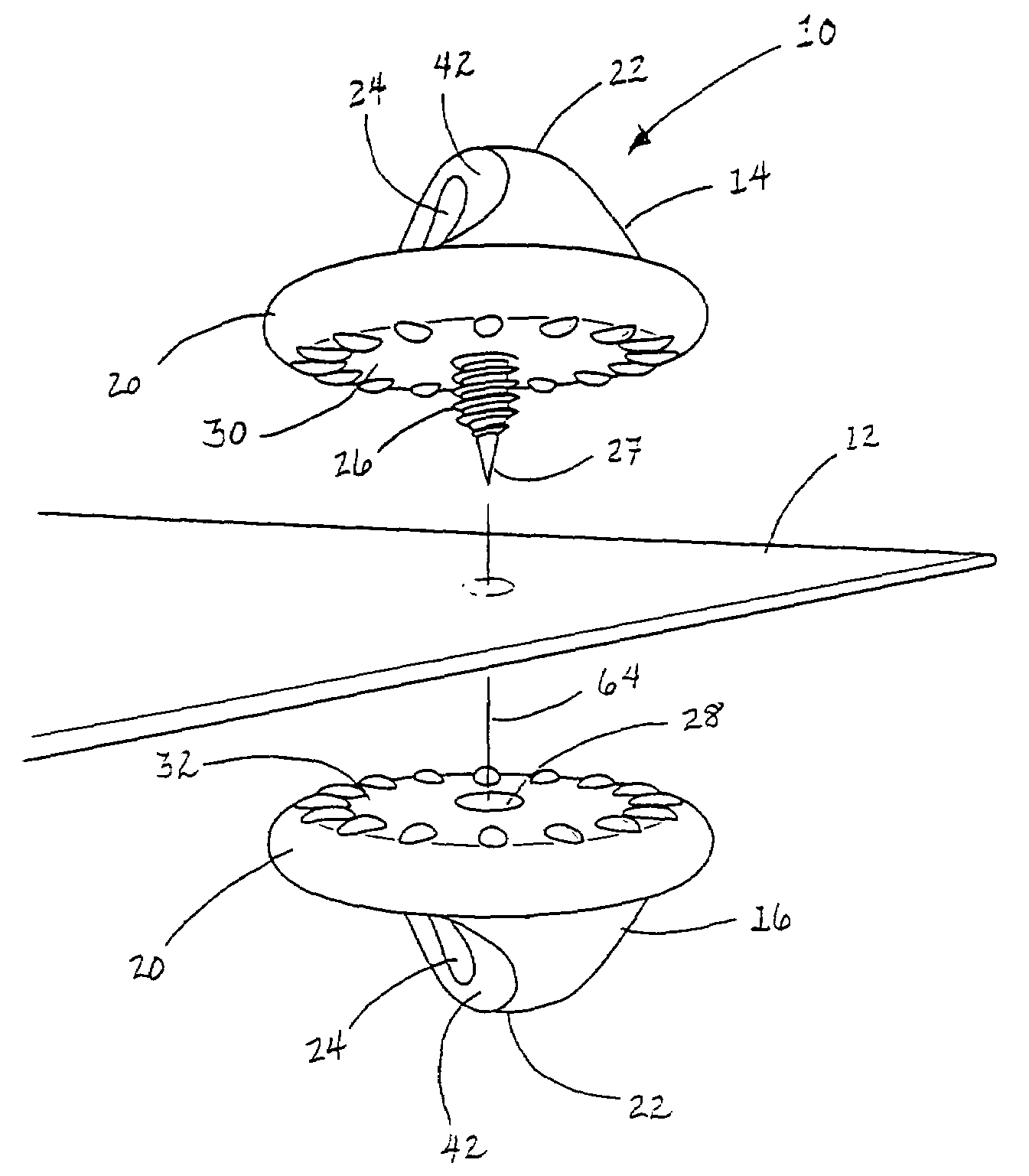
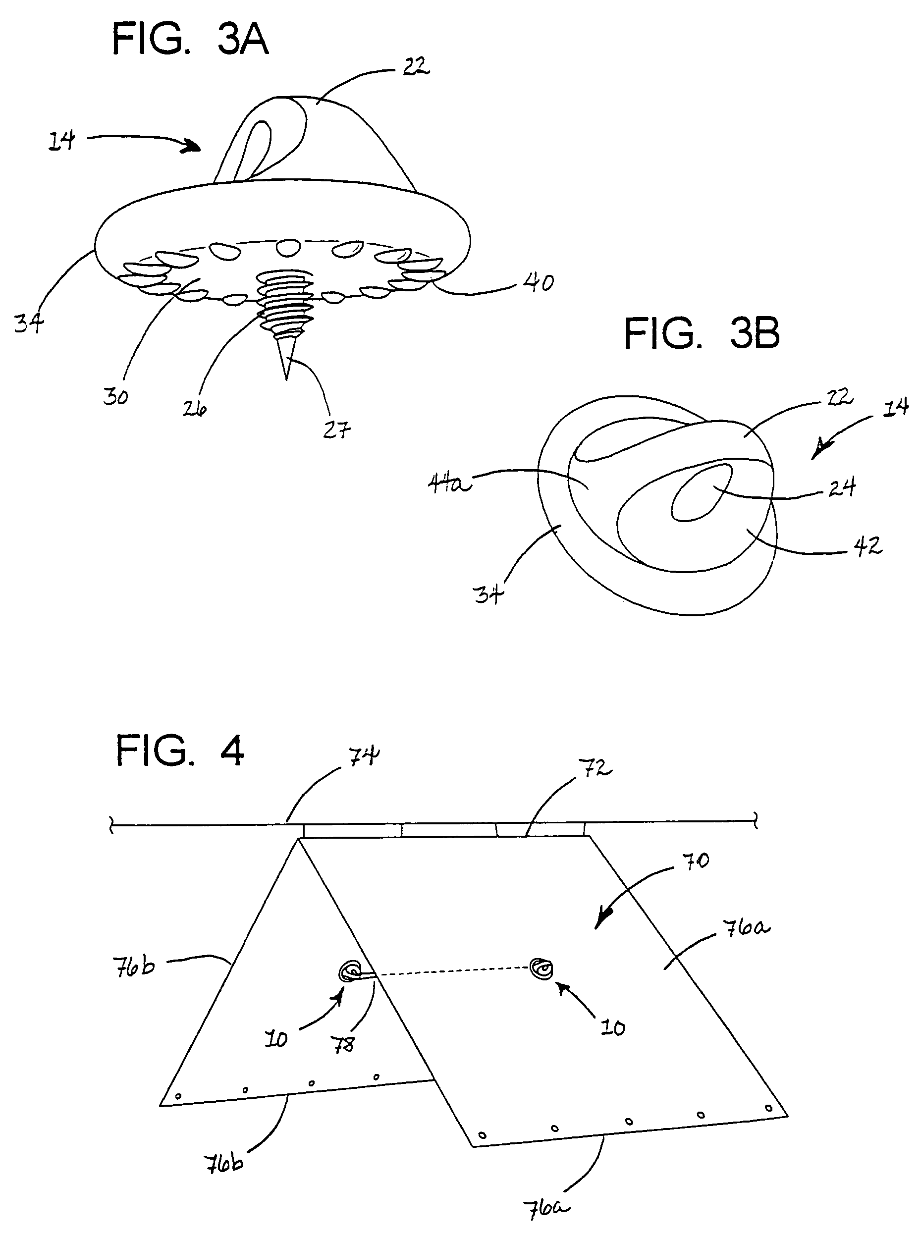
[0029]FIG. 1 shows a connector assembly 10 in accordance with a preferred embodiment of the present invention, and the manner in which this is attached to the panel of an exemplary tarp 12. As can be seen, the connector assembly includes male and female connector members 14, 16 that are positioned on opposite sides of the tarp.

[0030]The male and female connector members are generally similar in overall shape, in that each includes a generally flat, circular base portion 20 and an outwardly extending attachment portion 22 having an opening 24 for an attachment to a hook, rope, cord or the like. However, as can be seen in FIG. 1 and also FIG. 2, the male connector member 14 is provided with a central screw portion 26 that extends normal to the base surface and is provided with a tapered, sharply pointed tip 27 for piercing the material of tarp 12. The female connector member 16, in turn, includes a central, internally threaded socket portion 28 for receiving the screw portion 26 in th...


PUM


Abstract

A connector assembly that enables a rope or other load to be attached to a tarp or other sheet material. The assembly includes male and female connector members having broad, flat base surfaces for engaging the material of the tarp from opposite sides. The male connector member has a sharply pointed screw portion for penetrating through the material of the tarp, and the female connector member has a threaded socket for receiving the screw portion of the male connector member. At least one of the connector members includes a projecting flange portion having an opening or hook for attachment of the rope or other load. The flange portions are flattened for being gripped between the thumb and forefinger when tightening / loosening the assembly. The grip faces of the connector members include raised protuberances that prevent accidental loosening during use.

Description

BACKGROUND[0001]a. Field of the Invention[0002]The present invention relates generally to accessories for use with tarps and similar sheet materials, and, more particularly, to a connector that mounts to the fabric or other material of a tarp so as to allow attachment of a load thereto.[0003]b. Related Art[0004]For ease of description and understanding the present invention is described herein primarily with reference to “tarps”. It will be understood, however, that as used in this description and the appended claims, the term “tarp” is not limited to tarpaulins of traditional construction and includes all thin, flexible sheets that are used to provide cover and for similar purposes, whether they are formed of woven or non-woven material. Also included are articles and structures that incorporate or are constructed of tarp materials, such as tents and similar enclosures.[0005]As is well known, tarps provide useful coverings for a vast range of purposes. Just a few examples include t...

Claims


Application Information

Patent Timeline
Patent Type & Authority Patents(United States)
IPC IPC(8): E04H15/62E04H15/64F16B5/06F16B45/00
CPCE04H15/64F16B5/0692Y10T403/5741Y10T403/7062Y10T24/3653F16B45/00F16B45/002F16B45/008
Inventor CAMERON, ROBERT W
Owner NEVADA NORTH COAST LIMTIED
Learn More