
Medical forceps

a technology of forceps and splints, applied in the field of medical forceps, can solve the problems of limited field of view of optics arranged in the inside of the inner shank, and achieve the effects of reliable cutting or separation of tissue, simple positioning of forceps during an operation, and secure grip

Inactive Publication Date: 2007-03-06
RICHARD WOLF GMBH
View PDF24 Cites 26 Cited by
  • Summary
  • Abstract
  • Description
  • Claims
  • Application Information

AI Technical Summary

Benefits of technology

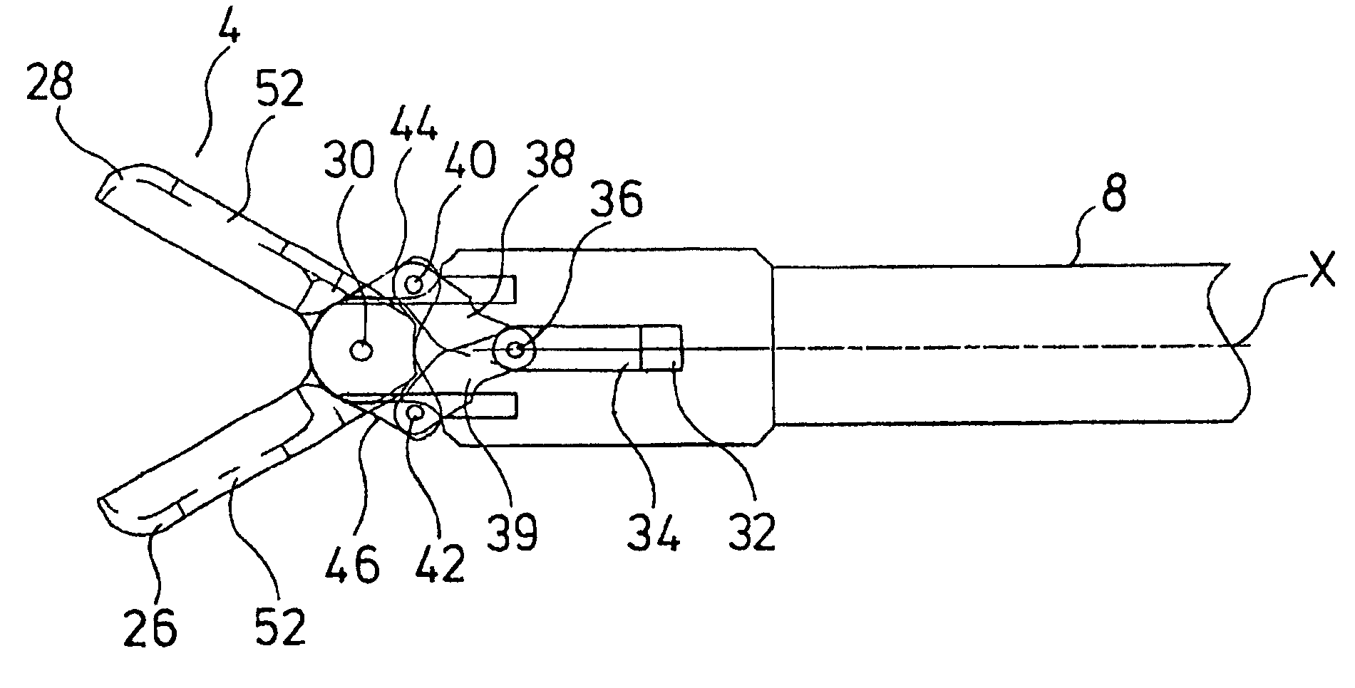
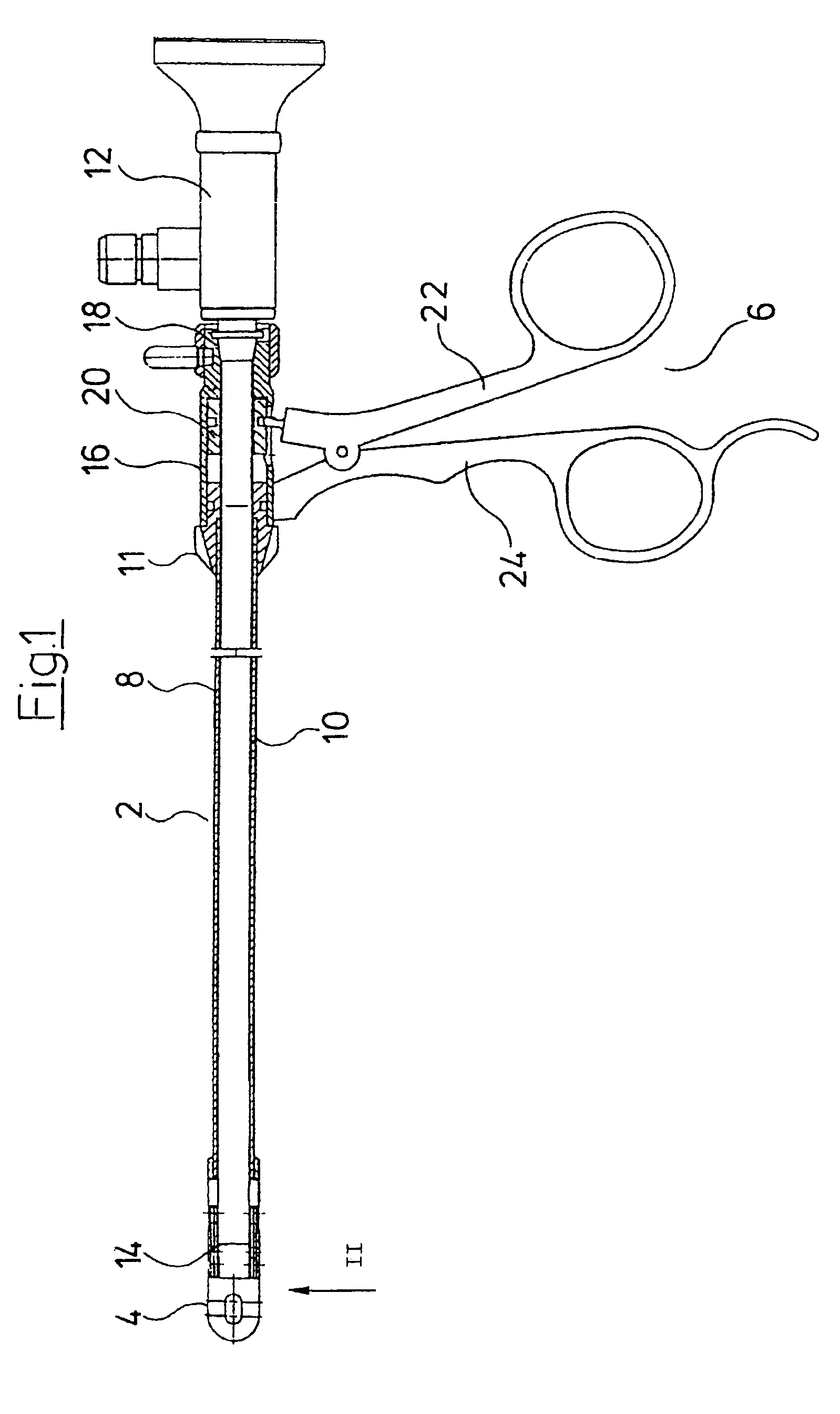
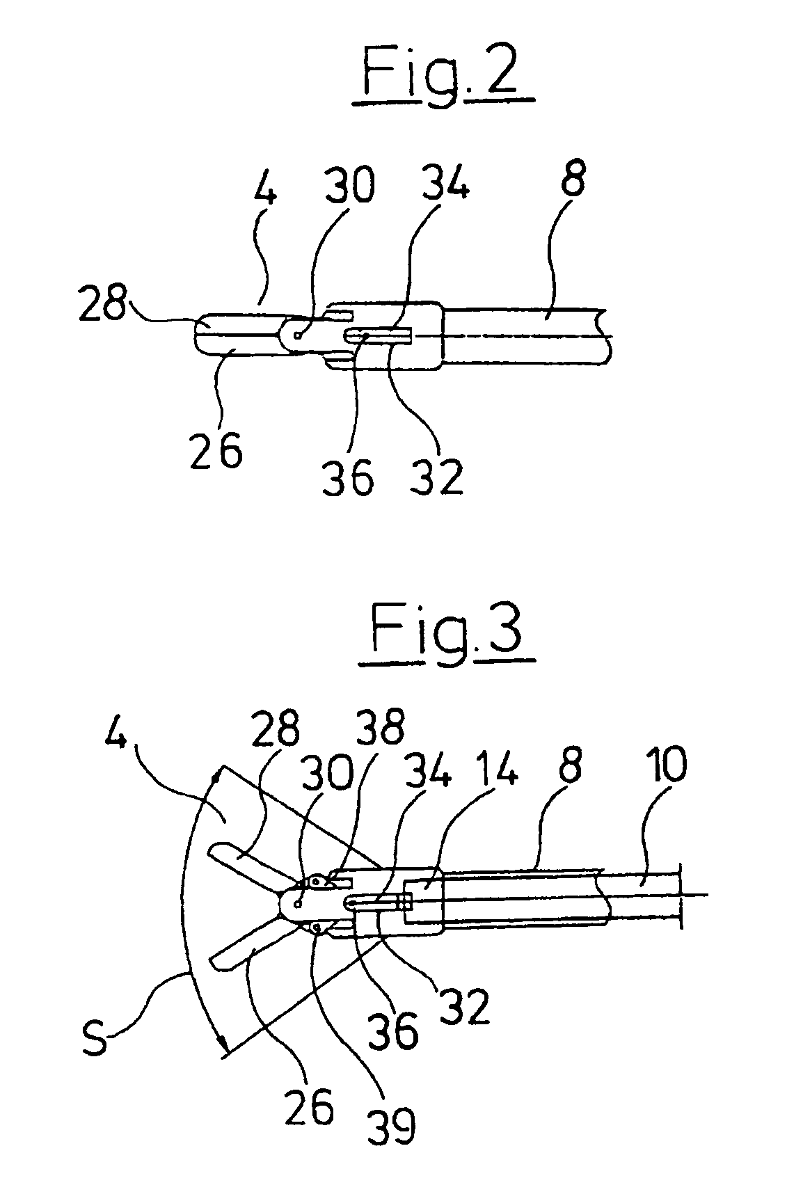
[0005]The medical forceps according to the invention comprises a tubular outer shank on whose distal end there is formed a forceps jaw with two jaw parts. The tubular outer shank preferably has a circular cross section and the two jaw parts together likewise preferably form a circular cross section of essentially the same diameter as the outer shank. The two jaw parts are each rotatably mounted on the outer shank on two opposite sides, i.e., preferably two sides lying diametrically opposite one another. Furthermore, in the tubular outer shank there is arranged a tubular inner shank for actuating the jaw parts. The tubular inner shank extends in the longitudinal direction parallel to the outer shank. At the same time, the tubular inner shank preferably has an outer contour which is designed corresponding to the inner contour of the outer shank, so that the inner shank is slidingly guided in the inside of the outer shank. The inner shank is coupled to the two jaw parts for their actuation via two lever systems. The lever systems convert the movement of the inner shank in the longitudinal direction into a pivoting or rotational movement of the two jaw parts. For this purpose, each of the lever systems is linked to the jaw part, one on each of the two sides lying opposite one another. This means the lever systems for opening and closing the jaw parts are arranged on the same sides of the forceps on which the mountings for the pivotable jaw parts are also provided. The mounting and actuation elements for the jaw parts are thus extremely compact and arranged tightly next to one another. This permits the mounting and actuation elements for the jaw parts to be designed slim in profile and compactly. Since the lever systems are arranged laterally on the forceps, it is not necessary for the elements of the jaw parts or the lever systems to project into the inside of the outer or inner shank on opening the forceps jaw parts. This means the inner space of the inner shank, as well as the region located in front of the opening of the inner shank on its distal end, may be kept free even when the forceps jaw is open, in order to ensure the largest possible field of view for optics applied into the inner shank. By way of the linkage on both sides or the engagement of a lever system on each jaw part on both sides, one may furthermore transmit a large force onto the jaw parts, so that a large forceps force may be made available, for example for separating tissue parts. The arrangement of two jaw parts permits a very large angle of opening of the jaw part, whereby on the one hand, the gripping of difficultly accessible or large tissue parts is favored, and on the other hand, the field of view through the open forceps jaw is very large.
[0017]In a preferred embodiment, an opening may be formed in at least one of the two jaw parts. Such an opening permits one to look through the forceps jaw from the inside of the forceps or the inner shank even when the forceps jaw is closed. In this manner, the positioning of the forceps during an operation may also be simplified when the forceps jaw is closed. The opening is preferably arranged in the middle of the jaw part spaced from its outer or cutting edge, so that furthermore, a secure grip or a reliable cutting or separation of tissue by the forceps is ensured.

Problems solved by technology

In this way, when the forceps is open, the field of view for optics arranged in the inside of the inner shank is very greatly limited.

Method used


Image

  • Medical forceps
  • Medical forceps
  • Medical forceps

Examples


Embodiment Construction

[0029]FIG. 1 shows in a sectioned view the total view of the forceps according to the invention. The medical forceps comprises a forceps shank 2 at whose distal end there is arranged a forceps jaw 4 and at whose proximal end there is arranged a forceps handle 6. The forceps shank 2 consists of an outer shank 8 and of an inner shank 10 arranged in the inside of the outer shank. The outer shank 8 and the inner shank 10 are tubular, in particular formed with a circular cross section. At the same time the inner shank 10 has an outer diameter which essentially corresponds to the inner diameter of the outer shank 8. This permits the inner shank 10 to be guided in the outer shank 8 in a fitting manner and essentially free of play or with little play. The optics 12 extend from the proximal end of the forceps into the inner shank 10 and through this preferably up to the distal end 14 of the inner shank 10 in order to permit an observation of the region surrounding the forceps jaw 4 or of the...


PUM


Abstract

A medical forceps is provided with a tubular outer shank, on whose distal end there is formed a forceps jaw with two jaw parts. The two jaw parts are each rotatably mounted on the outer shank at two sides opposite one another. A tubular inner shank for actuating the jaw parts is displaceably arranged in the inside of the outer shank in its longitudinal direction. The inner shank is coupled to the two jaw parts for their actuation via two lever systems. Each of the lever systems is linked to the two jaw parts, one lever system on each of the two opposite sides.

Description

CROSS REFERENCE TO RELATED APPLICATION[0001]This application claims priority from German patent application 101 56 313.2, filed Nov. 19, 2001.BACKGROUND OF THE INVENTION[0002]The invention relates to a medical forceps.[0003]There are known medical forceps, which comprise a hollow shank into which, for example, an optical system is applied. From German published patent application DE 44 44 403 A1 there is known, for example, a medical forceps which comprises a hollow shank on whose end there is arranged a pivotable forceps jaw part. The opening and closing of the forceps jaw part is effected via an inner shank longitudinally movable in the inside of the shank. This inner shank engages centrally on the upper side of the forceps jaw part. The forceps jaw part in the lower region is rotatably linked onto the outer shank on two sides. By displacing the inner shank in the longitudinal direction of the forceps shank, the point of engagement of the inner shank on the forceps jaw part is rad...

Claims


Application Information

Patent Timeline
IPC IPC(8): A61B17/29A61B17/28A61B19/00
CPCA61B17/29A61B2017/2902A61B2017/2939A61B90/361
Inventor PRESTEL, STEPHAN
Owner RICHARD WOLF GMBH
Learn More