
Brake caster with stroke adjustment mechanism

a technology of stroke adjustment and brake caster, which is applied in the direction of brake systems, mechanical equipment, transportation and packaging, etc., can solve the problems of increasing operation costs and wheeling, and achieve the effect of prolonging the service life of the caster and reducing the operation cos

Inactive Publication Date: 2007-02-27
LIN CHING SUNG
View PDF5 Cites 30 Cited by
  • Summary
  • Abstract
  • Description
  • Claims
  • Application Information

AI Technical Summary

Benefits of technology

[0006]The primary objective of the present invention is to provide a brake caster that incorporates a stroke adjustment mechanism to allow the user to tune the brakes of a hand cart according to different levels of rubber on the wheels, so that the service life of the casters can thus be prolonged without numerous replacements of the wheels, and the operation costs can be considerably reduced.
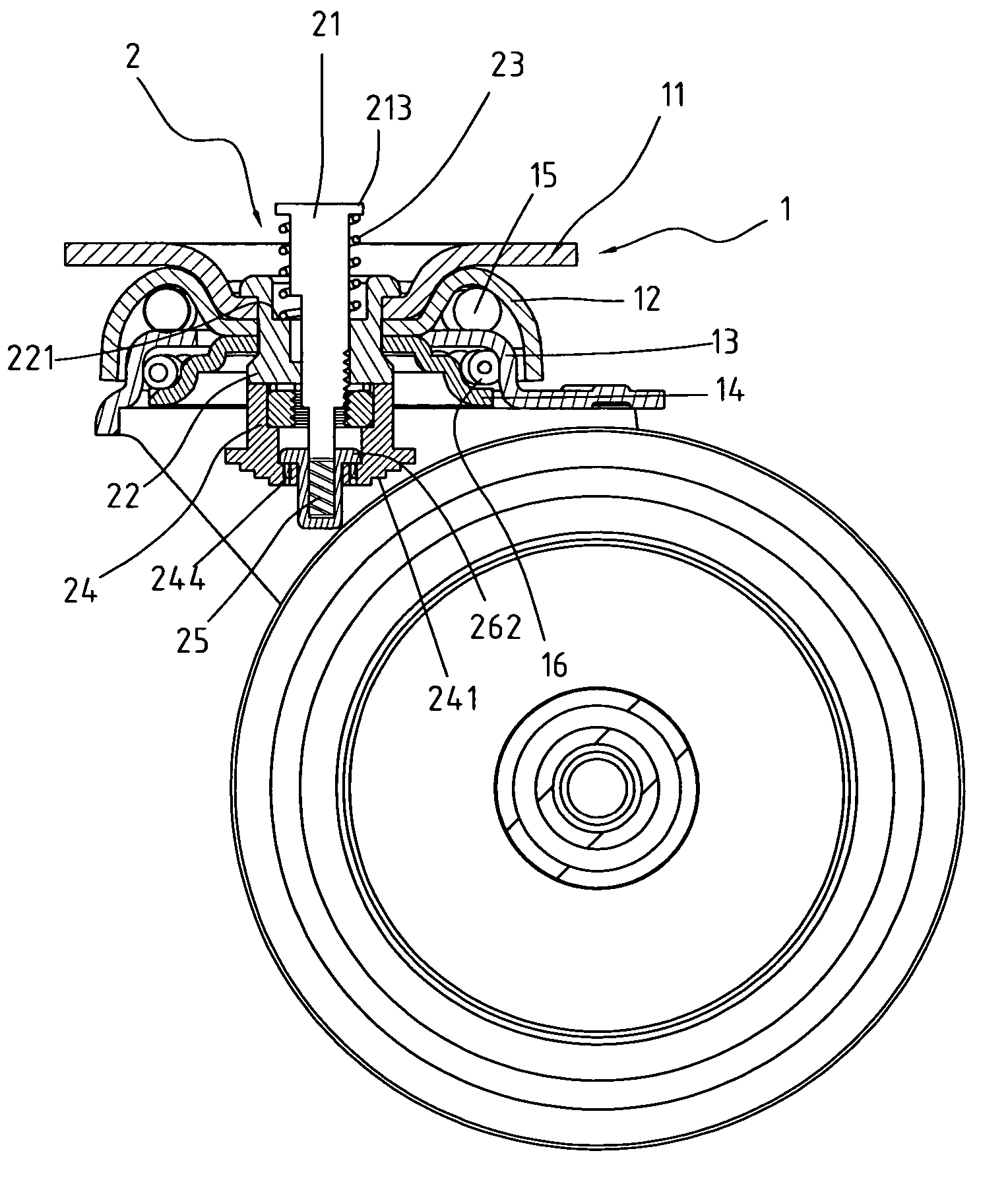
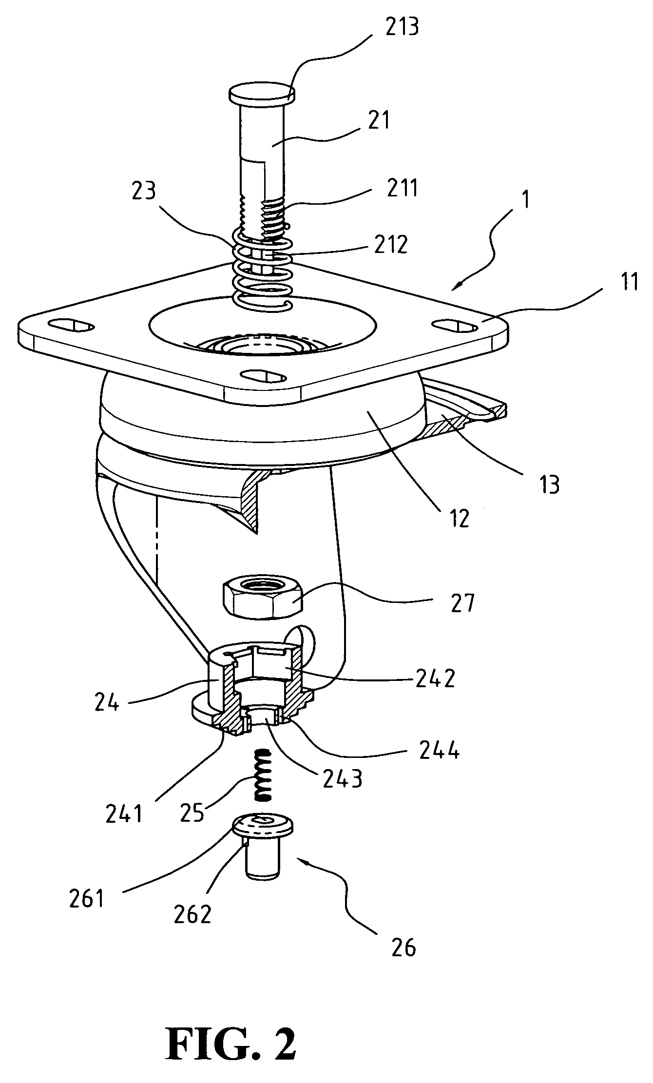
[0008]Another characteristic of the invention is the structure of the king pin with outward threads around the neck, and the plunger block with inward threads on the inner wall, which is connected with a brake pad on the bottom end. This structure allows the user to adjust the stroke distance by twisting the plunger block in and out around the king pin lengthwise.
[0014]The king pin has outward threads on the outer wall, and the plunger block is fitted with a polygonal lock nut that has inward threads on the inner wall, so that the plunger block can be slipped onto the king pin along the threads to adjust the position of the brake pad. The stroke distance can thus be appropriately adjusted according to different levels of rubber on the wheel, so that the service life of the caster can be prolonged without numerous replacements of the casters and wheels.

Problems solved by technology

To repair the hand cart under these conditions, the conventional way simply to replace the wheels of the casters, but numerous replacements of the wheels will definitely increase the operation cost.

Method used


Image

  • Brake caster with stroke adjustment mechanism
  • Brake caster with stroke adjustment mechanism
  • Brake caster with stroke adjustment mechanism

Examples


Embodiment Construction

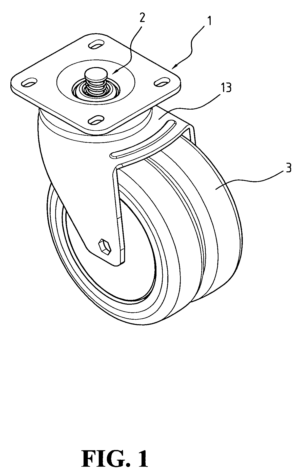
[0022]Referring to FIG. 1, a brake caster constructed in accordance with the present invention comprises a swivel module 1 formed with a top plate 11, two raceways 12, 13 with two layers of ball bearings 15, 16, a hub 2, two fork legs (not labeled) on two sides, and a wheel 3 fixed between the two fork legs.

[0023]Referring to FIG. 3, the swivel module 1 includes a base plate 14, a lower raceway 13, an upper raceway 12, and a top plate 11 each being stacked over the other, where the two raceways 12, 13 and the base plate 14 together forms the traveling paths for the two layers of ball bearings 12, 13, together forming the yoke.

[0024]The hub 2 of the caster is the main focus of the present invention, and the rest of the components are very similar to those found in a standard caster. Since their structures and functions have been amply covered by other papers, the topic will not be discussed in the present disclosure.

[0025]The structure of the hub 2, as shown in FIG. 3, is directly re...


PUM


Abstract

Disclosed is a brake caster with stroke adjustment mechanism, including a retainer, a king pin, a catch spring, a catch / release button, a plunger block, and a brake pad. The upper part of the king pin is fitted with the spring coil; the catch / release button is fitted with the catch spring; and a threaded polygonal lock nut is placed over the catch / release button in the hollow space of the plunger block, which has the brake pad installed on the bottom end; the plunger block being coupled with the catch / release button is slipped onto the king pin lengthwise along the threads. By twisting the plunger block in and out around the neck of the plunger block, the stroke distance can be adjusted according to different levels of rubber on the wheel, so that the service life of the caster can be effectively prolonged without numerous replacements of the wheels.

Description

BACKGROUND OF THE INVENTION[0001]1. Field of the Invention[0002]The present invention relates to a brake caster for hand carts, in particular to a brake caster installable on hand carts, which uses a stroke adjustment mechanism to tune the brake so as to extend the service life of the caster without numerous replacements of the wheels.[0003]2. The Related Art[0004]The hand carts are used in shopping malls, large plazas, and airports, which provide a convenient means of transporting bulky or heavy merchandise, cargo or luggage. To steer and stop the hand carts efficiently, many are equipped with hand brakes. The hand brake actually uses the brake casters installed on the bottom of the hand cart, and mechanically connected through a connecting means to a handle bar disposed above the rack, to allow the user to control the brake with the hands. Once the handle bar is depressed, the brake is released and the hand cart is then free to move forward or backward, but when the external force...

Claims


Application Information

Patent Timeline
Patent Type & Authority Patents(United States)
IPC IPC(8): B60B33/04B60T1/00F16D65/42F16D65/46
CPCB60B33/0018B60B33/0039B60B33/0049B60B33/0057B60B33/0068B60T1/04B60B33/0081B60B33/021B60B33/023B60B33/025B60B33/0073
Inventor CHUNG, CHIA-LIANG
Owner LIN CHING SUNG
Learn More