
Washing machine

a washing machine and dial knob technology, applied in other washing machines, contact mechanisms, textiles and paper, etc., can solve the problems of difficult to provide the reliance on the stability of the washing machine product, the dial knob may not be smoothly rotated, etc., and achieve the effect of reducing the movemen

Active Publication Date: 2007-02-20
SAMSUNG ELECTRONICS CO LTD
View PDF9 Cites 14 Cited by
  • Summary
  • Abstract
  • Description
  • Claims
  • Application Information

AI Technical Summary

Benefits of technology

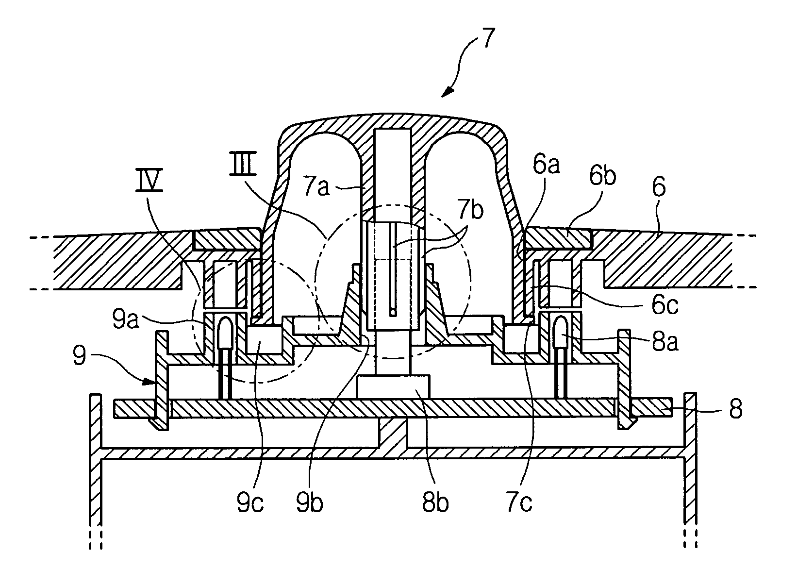
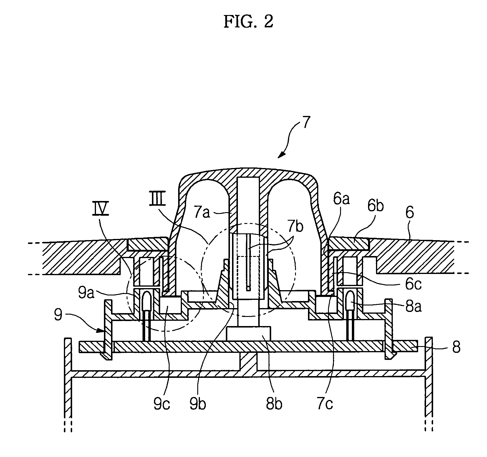
The invention provides a washing machine with a smooth-rotating dial knob and reduced movement in the radial direction. This is achieved through the use of shaft support ribs that are interposed between the rotary shaft and the shaft receiving hole, and which reduce the tilting of the dial knob. Additionally, the invention includes a ring-shaped support portion and upper and lower support ribs to further reduce the tilting of the dial knob. These features improve the overall stability and functionality of the washing machine.

Problems solved by technology

When the interval between the outer cylindrical surface of the rotary shaft and the inner cylindrical surface of the shaft receiving hole is broad, the dial knob moves in the radial direction through the interval, and it is difficult to provide the reliance on stability of the washing machine product.
On the other hand, when the interval between the outer cylindrical surface of the rotary shaft and the inner cylindrical surface of the shaft receiving hole is narrow, the outer cylindrical surface of the rotary shaft easily rubs against the inner cylindrical surface of the shaft receiving hole, and the dial knob may not be smoothly rotated.

Method used


Image

  • Washing machine
  • Washing machine
  • Washing machine

Examples


Embodiment Construction

[0027]Reference will now be made in detail to an exemplary embodiment of the present invention, an example of which is illustrated in the accompanying drawings, wherein like reference numerals refer to like elements throughout. The embodiment is described below to explain the present invention by referring to the annexed drawings.

[0028]In the exemplary embodiment, the present invention is applied to a drum washing machine.

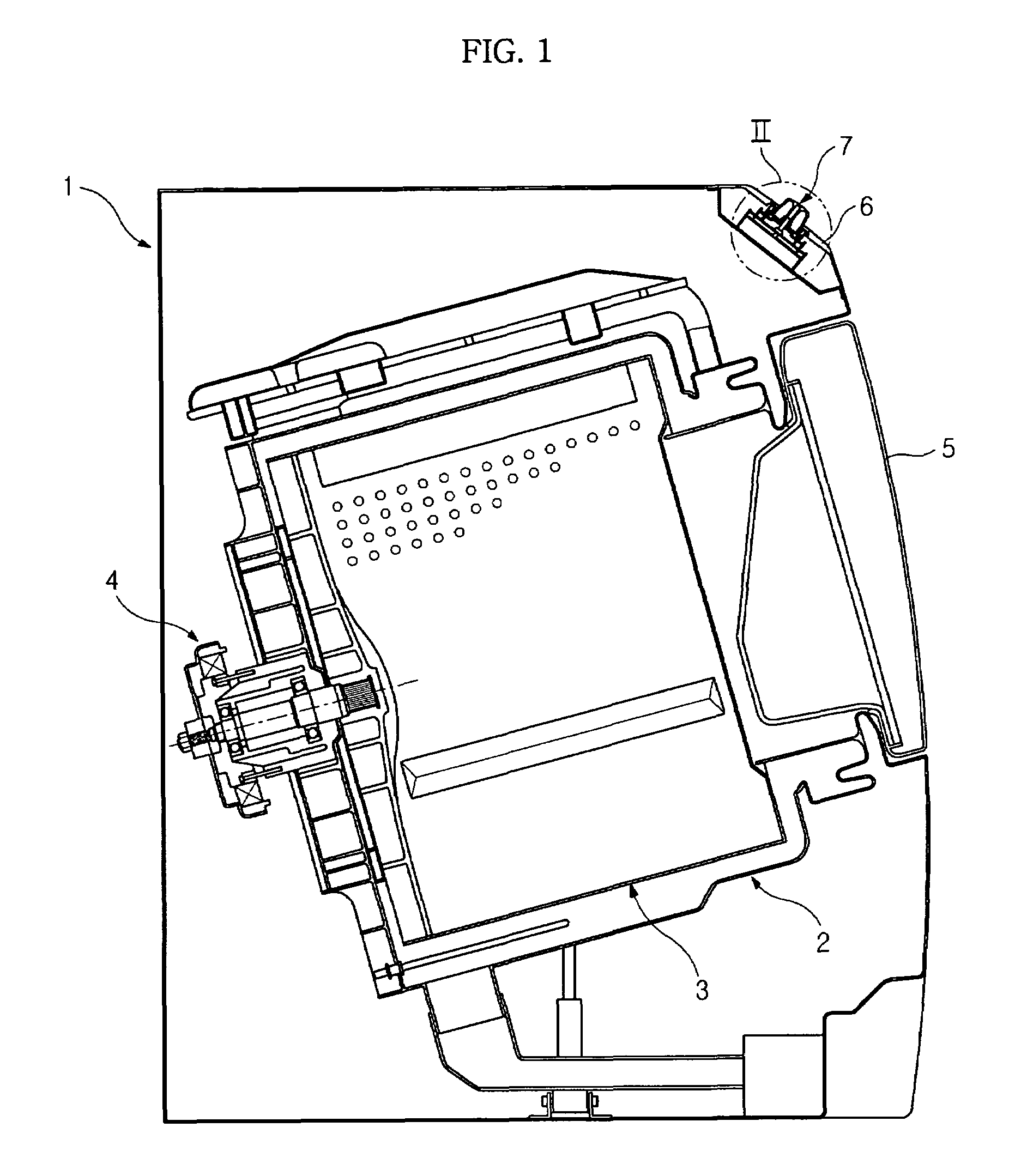
[0029]A drum washing machine, to which the present invention is applied, as shown in FIG. 1, comprises a tub 2 suspended in a housing 1 forming the external appearance of the washing machine and for containing water, and a drum 3 rotatably installed in the tub 2 and rotated by a driving motor 4 and for containing laundry to be washed. The laundry contained in the drum 3 is lifted and dropped by the rotation of the drum 3, thereby being washed.

[0030]Front surfaces of the tub 2 and the drum 3 are opened so that the laundry is put into or taken out of the washing mach...


PUM


Abstract

A washing machine for reducing the movement of a dial knob. The washing machine comprises a control panel disposed on one side of a housing forming the external appearance of the washing machine, and provided with a circuit board installed therein for controlling the operation of the washing machine; a rotary switch installed on the circuit board and rotated for allowing a user to select functions of the washing machine; a dial knob passing through the control panel for transmitting external force to the rotary switch; a rotary shaft for transmitting the force from the dial knob to the rotary switch; a shaft receiving hole, in which the rotary shaft is installed; and shaft support ribs interposed between the rotary shaft and the shaft receiving hole for reducing the movement of the dial knob in the radial direction.

Description

CROSS-REFERENCE TO RELATED APPLICATION[0001]This application claims priority from Korean Patent Application No. 2005-9650, filed Feb. 2, 2005, in the Korean Intellectual Property Office, the disclosure of which is incorporated herein by reference.BACKGROUND OF THE INVENTION[0002]1. Field of the Invention[0003]The present invention relates to a washing machine and, more particularly, to a washing machine, in which the movement of a dial knob is reduced.[0004]2. Description of the Related Art[0005]Generally, a washing machine is an apparatus, which washes laundry by repeating washing and rinsing operations. The washing machine performs the washing of the laundry by lifting and dropping the laundry, or using friction between the laundry.[0006]A washing machine, which is disclosed in Korean Patent Laid-open Publication No. 10-2002-0020329, comprises a control panel, which is installed on the upper portion of the front surface of a housing forming the external appearance of the washing m...

Claims


Application Information

Patent Timeline
Patent Type & Authority Patents(United States)
IPC IPC(8): H01H13/00
CPCH01H43/10H01H19/005H01H19/025D06F34/30D06F37/20H01H19/14
Inventor SEO, JEONG KI
Owner SAMSUNG ELECTRONICS CO LTD
Learn More