
Bi-directional cerebral interface system

Inactive Publication Date: 2007-02-13
OSORIO IVAN +1
View PDF12 Cites 139 Cited by
  • Summary
  • Abstract
  • Description
  • Claims
  • Application Information

AI Technical Summary

Benefits of technology

[0029]The bi-directional cerebral interface system, described herein, provides for the safe, ergonomic, cost-effective and energy efficient implantation of a housing device for automated sensing and control of changes in brain states, considerably improving the state of the art.PRINCIPAL OBJECTS AND ADVANTAGES OF THE INVENTION
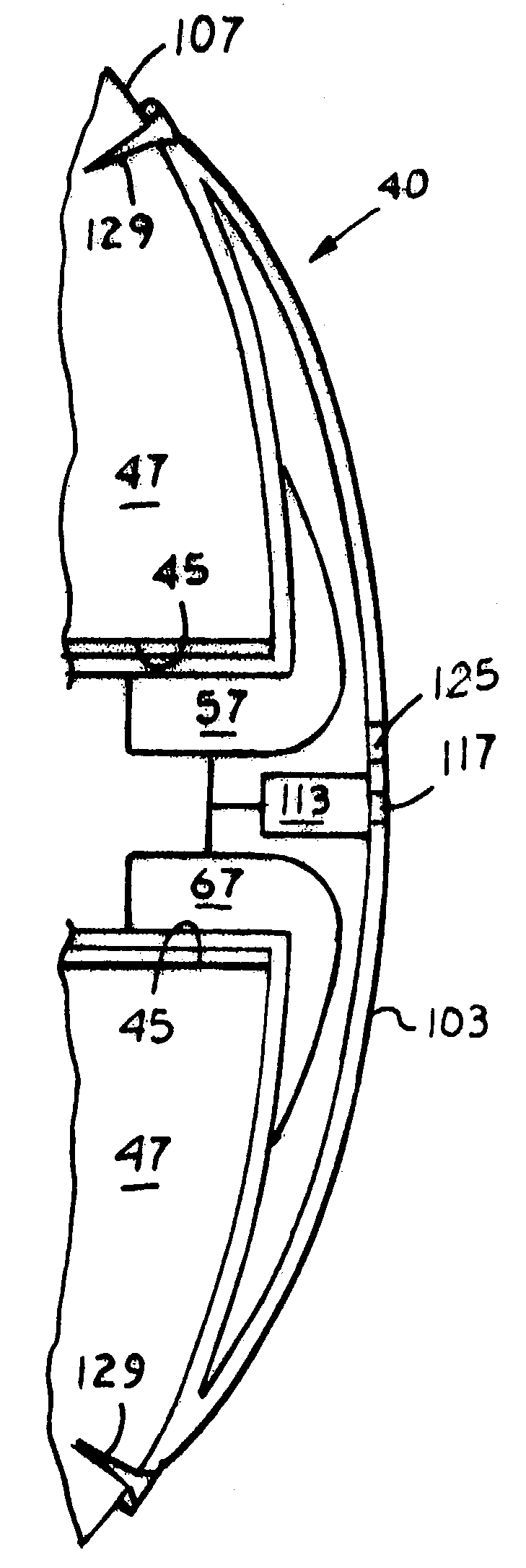
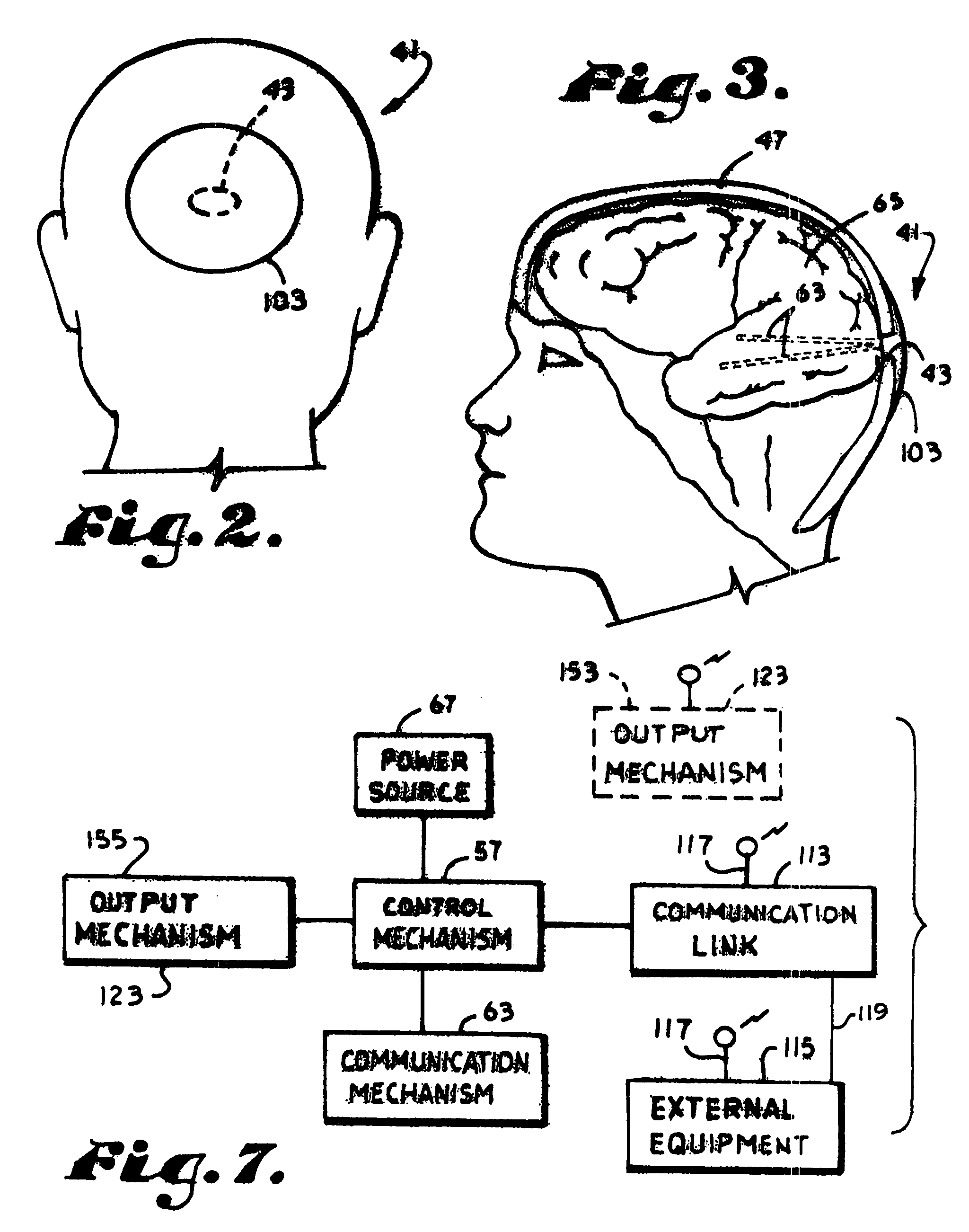
[0030]The principal objects and advantages of the present invention include: providing a brain access or cerebral interface mechanism mountable in a cavity formed in a subject's skull; providing such a cerebral interface mechanism having a housing mechanism preferably constructed of titanium; providing such a cerebral interface mechanism having an auxiliary housing portion extending tangentially outwardly from such a cavity; providing such a cerebral interface mechanism having a sealing mechanism for providing a fluid-tight seal between a housing mechanism thereof and the subject's skull; providing such a cerebral interface mechanism having a control mechanism, such as a programmed signal processor or microprocessor, spaced therein; providing such a cerebral interface mechanism having a communication mechanism for connecting a control mechanism thereof to the subject's brain; providing such a cerebral interface mechanism having a power source; providing such a cerebral interface mechanism having an inner wall aligned substantially co-planar with the surrounding inner surface of the subject's skull; providing such a cerebral interface mechanism having a communication link for wirelessly connecting a control mechanism thereof to external apparatus; providing such a cerebral interface mechanism having a control mechanism for activating an output mechanism; providing such a cerebral interface mechanism securable to the subject's skull by removable fastening means; and generally providing such a cerebral interface mechanism that is effective in operation, reliable in performance, capable of long operating life, and particularly well adapted for the proposed usages thereof.

Problems solved by technology

For example, the use of wires or conductors to carry a signal into or out of the brain, requires a special, time consuming procedure and careful placement of wires and connectors to avoid scalp / skin erosion, a common and serious complication which often requires removal of the device with loss of benefit to the subject.
More specifically, such an approach has several significant disadvantages: (i) the long conductors for connecting the device to electrodes implanted in the brain require tunneling under the scalp and skin, thereby requiring prolonged surgical and anesthesia for installation; (ii) the tract along the conductors often becomes infected requiring, in many cases, that the conductors be explanted with consequent cessation of treatment to the subject; (iii) the conductors often erode the overlying scalp, forcing removal of the cables so that healing can take place but, at the same time, removing the means for warning of or treating impending abnormal activities; (iv) the conductors often fracture since they are subjected to torsional and other forces generated by normal head / neck movements with consequent corrective surgery to replace the faulty conductors; and (v) in the case of telemetered signals, closer proximity of the emitter to the receiver would increase fidelity of the transmitted signals and decrease power requirements, hence prolonging battery life and decreasing frequency of surgical replacement procedures.
The placement of prior art brain devices outside the skull, such as in the infra-clavicular regions, is due to lack of space between the brain and the skull to position such devices and also to the inability to convert virtual into real spaces without affecting the integrity of the skull.
Accurate and reproducible prediction of behavioral or biologic signal changes associated with abnormal brain activities has not been generally possible as such events typically occur unpredictably.

Method used


Image

  • Bi-directional cerebral interface system
  • Bi-directional cerebral interface system
  • Bi-directional cerebral interface system

Examples


Embodiment Construction

[0041]As required, detailed embodiments of the present invention are disclosed herein; however, it is to be understood that the disclosed embodiments are merely exemplary of the invention, which may be embodied in various forms. Therefore, specific structural and functional details disclosed herein are not to be interpreted as limiting, but merely as a basis for the claims and as a representative basis for teaching one skilled in the art to variously employ the present invention in virtually any appropriately detailed structure.

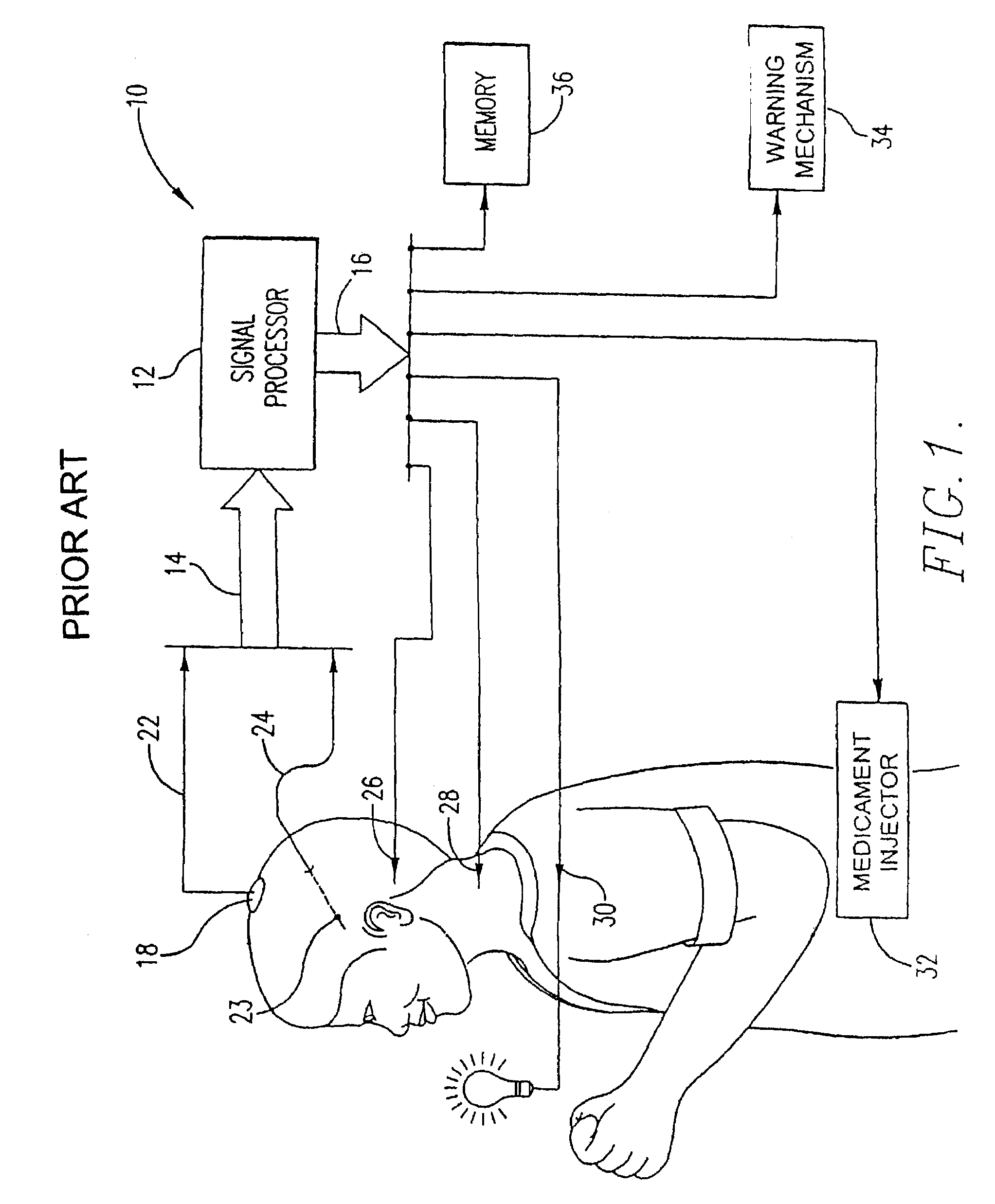
[0042]A detailed description of a prior art system for the prediction, rapid detection, warning, prevention, and control of changes in activity states in the brain of a subject has been previously disclosed in allowed U.S. patent application Ser. No. 08 / 778,771, which disclosure is incorporated herein by reference. FIG. 1 thereof, reproduced as FIG. 1 hereof, illustrates an apparatus 10 for receiving and analyzing signals representative of a subject's brain a...


PUM


Abstract

A cerebral interface system including a housing mechanism spaced at least partially in a cavity formed in the subject's skull; an attaching mechanism; a fluid-tight sealing mechanism; a control mechanism; a communication mechanism with one or more sensors embedded in the subject's brain connecting the control mechanism to the subject's brain; a power source; an inner wall substantially aligned with an inner surface of the subject's skull; an outer wall which may include an auxiliary portion extending tangentially outwardly from the cavity formed in the subject's skull; a communication link connecting the control mechanism to external apparatus for transmitting or receiving information related to detecting, predicting, controlling, or aborting abnormal brain activity of the subject; and an output mechanism which is activatable by the control mechanism.

Description

CROSS REFERENCE TO RELATED APPLICATIONS[0001]This application is a continuation application of U.S. application Ser. No. 09 / 416,471 filed Oct. 12, 1999, now U.S. Pat. No. 6,560,486, issued May 6. 2003; U.S. application Ser. No. 10 / 394,869 filed Mar. 22, 2003 is a divisional application of U.S. application Ser. No. 09 / 416,471 filed Oct. 12, 1999, now U.S. Pat. No. 6,560,486, issued May 6, 2003.BACKGROUND OF THE INVENTION[0002]1. Field of the Invention[0003]The present invention relates to the field of neuroscience and, more particularly without limitation, to a subfield of neuroprostheses for housing devices in close proximity to the brain.[0004]2. Glossary of Terms and Useful Definitions[0005]The term “electroencephalogram” (“EEG”) refers to voltage potentials recorded from the scalp and encompasses any recordings obtained from a source outside the dura mater. The term “electrocorticogram” (“ECoG”) refers to voltage potentials recorded intracranially, e.g., directly from the cortex....

Claims


Application Information

Patent Timeline
IPC IPC(8): A61N1/375A61B5/00A61B5/0205A61B5/026A61B5/03A61B5/0402A61B5/0476A61B5/0488A61B5/0496A61B5/053A61B5/07A61N1/36
CPCA61B5/0476A61B5/076A61B5/14546A61B5/6882A61N1/3605A61B5/02055A61N1/37217A61B5/031A61B5/0402A61B5/0488A61B5/0496A61B5/0531A61B5/14532A61N1/36082A61N1/375A61B5/026A61B5/4094A61N1/37518A61N1/37514A61B5/318A61B5/398A61B5/389A61B5/369A61B5/37A61B5/395
Inventor OSORIO, IVANFREI, MARK
Owner OSORIO IVAN
Learn More