
Motor control system for a surgical handpiece

a technology of motor control and handpiece, which is applied in the direction of electric motor speed/torque regulation, applications, surgery, etc., can solve the problems of increasing the chance of error, causing improper device selection and/or operation, and surgical personnel operating the handpiece at settings that are less than optimal

Active Publication Date: 2007-02-13
MEDTRONIC INC
View PDF23 Cites 793 Cited by
  • Summary
  • Abstract
  • Description
  • Claims
  • Application Information

AI Technical Summary

Benefits of technology

[0009]Another aspect of the present invention provides a method of controlling a powered surgical handpiece. The system includes a controller, a control console and a powered surgical handpiece capable of powering a micro-cutting instrument. The system detects whether the powered surgical handpiece is connected to the controller. The controller is operated to determine whether the micro-cutting instrument has been coupled to the power...

Problems solved by technology

However, with the substantial expansion in available procedures, the opportunity for improper device selection and / or operation has arisen.
That is to say, because a surgeon can now use a single handpiece with a variety of different micro-cutting instruments to perform a number of different procedures, it is possible that surgical personnel may inadvertently operate the handpiece at settings that are less than optimal for a particular surgical procedure.
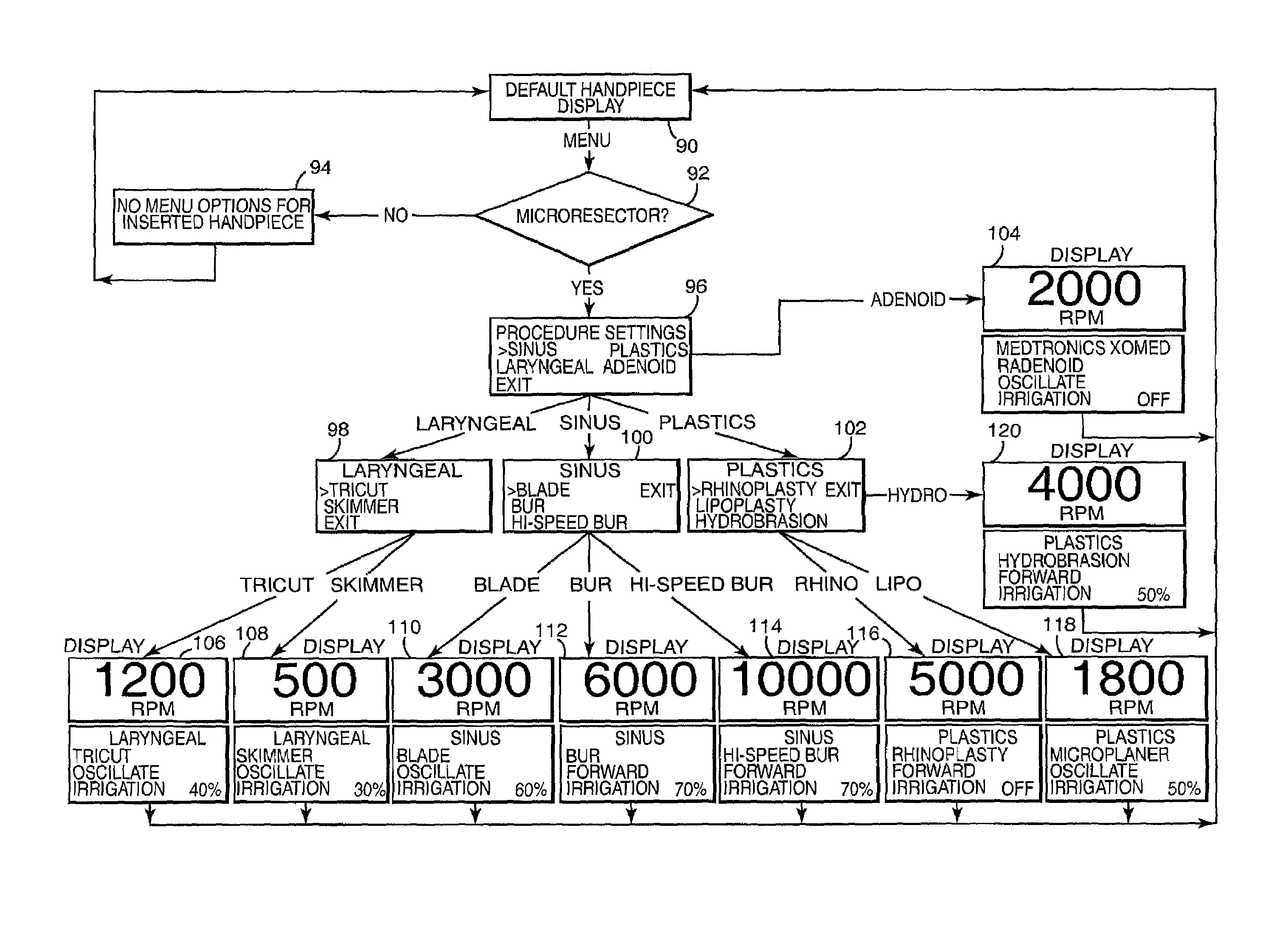
For example, a surgeon performing a laryngeal tricut procedure with a micro-resecting instrument may accidentally attempt to operate the powered handpiece at speeds well in excess of the recommended 1,200 rpm limit because the surgeon has failed to adjust the control panel settings from a previous, different procedure; surgical personnel have been unable to recall the preferred settings, etc.
Other operational settings, such as rotational mode (e.g., forward, reverse, oscillate), irrigation settings, etc., must also be determined and properly implemented by the surgical personnel, again increasing the opportunity for error.
However, the enhancement of available features may give rise to unintentional misoperation.

Method used


Image

  • Motor control system for a surgical handpiece
  • Motor control system for a surgical handpiece
  • Motor control system for a surgical handpiece

Examples


Embodiment Construction

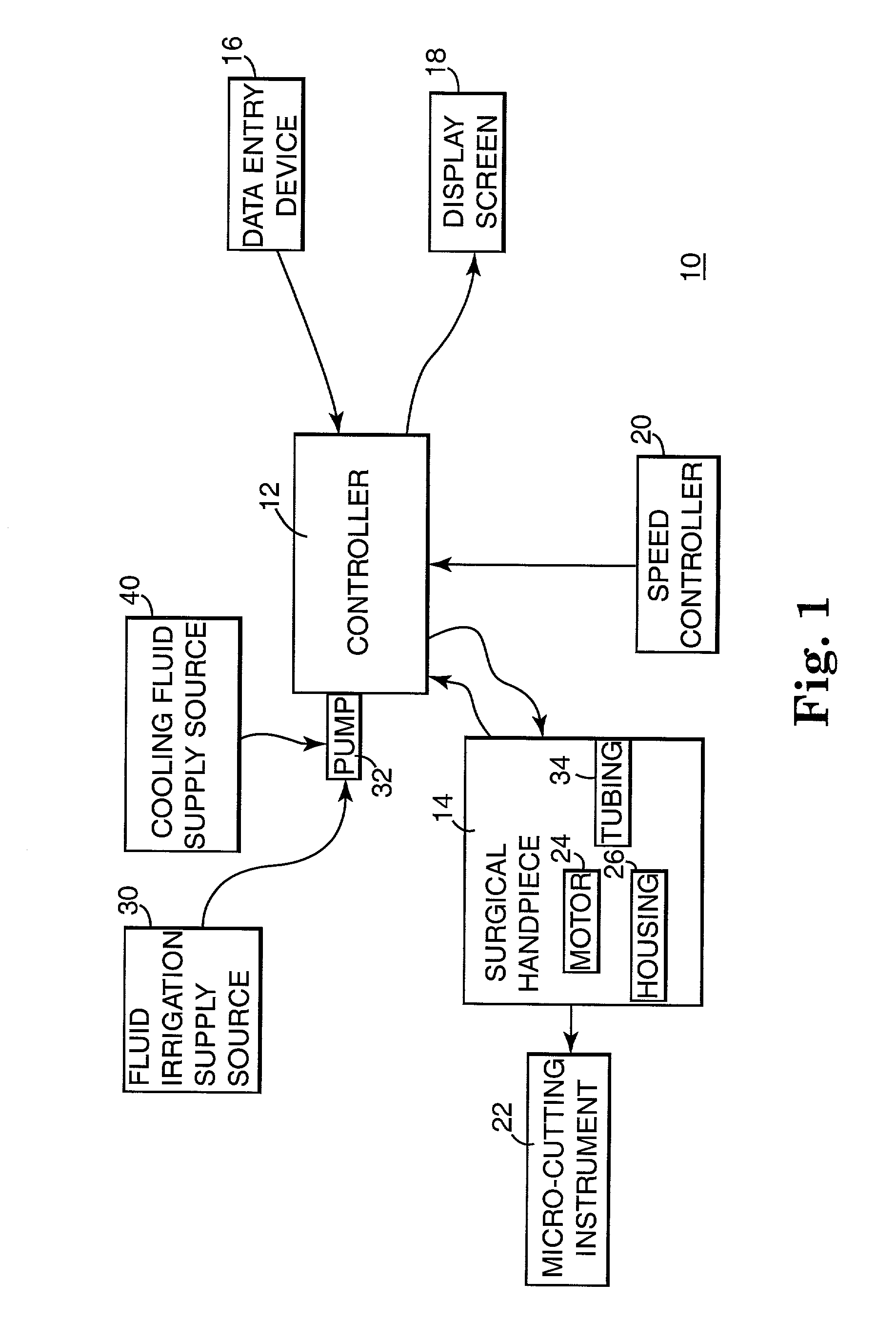
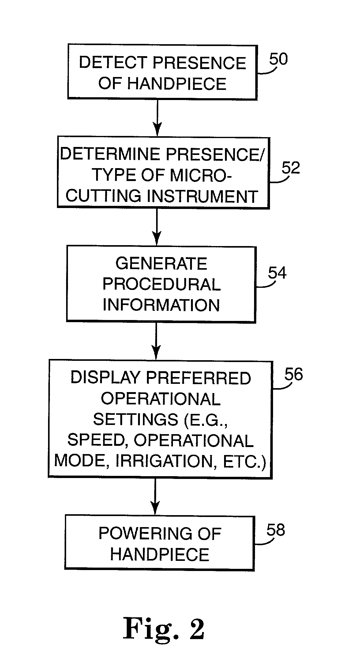
[0016]One preferred embodiment of a powered surgical handpiece control system 10 is illustrated in block form in FIG. 1. The control system 10 includes a controller 12, a powered surgical handpiece 14, a data entry device 16, a display screen 18, and a speed controller 20. The various components of the control system 10 are described in greater detail below. In general terms, however, the handpiece 14, the data entry device 16, the display screen 18, and the speed controller 20 are electrically connected to the controller 12. During use, the controller 12 detects the presence of the powered handpiece 14, and receives procedural information from surgical personnel (not shown) via the data entry device 16. Based upon this information, the controller 12 displays operational information to the surgical personnel at the display screen 18. Depending upon the particular procedure to be performed, the controller 12 may request and receive additional procedural information from the surgical ...


PUM


Abstract

A system and method for powered surgical handpiece capable of powering various micro-cutting instruments is described. The system is comprised of a controller adapted for controlling / interfacing with a powered surgical handpiece based upon user-defined procedural information. A data entry device is used for entering the user-defined procedural information used by the controller for configuring and operating the motor control system.

Description

CROSS-REFERENCE TO RELATED APPLICATION[0001]This application claims the benefit of, and incorporates herein by reference the entirety of, U.S. Provisional Application Ser. No. 60 / 235,217, filed on Sep. 24, 2000.BACKGROUND OF THE INVENTION[0002]The present invention generally relates to powered handpieces for driving surgical cutting instruments. More particularly, it relates to a control system for interfacing with a powered surgical handpiece and controlling operation thereof.[0003]Powered surgical handpieces are commonly used in many medical specialties to drive surgical blades or cutting instruments for performing various diverse cutting functions including resection, comminution, dissection, debridement, shaving, drilling, pulverizing, and shaping of anatomical tissue. In the areas of ENT / head / neck surgery, the handpieces are typically configured for selective coupling to, and driving of, a variety of different micro-cutting surgical instrument design to perform a specific proce...

Claims


Application Information

Patent Timeline
IPC IPC(8): H02P5/00A61B17/00A61B17/16A61B19/00
CPCA61B17/1626A61B17/00234A61B19/5225A61B2017/00017A61B2017/00115Y10S388/935A61B2017/00225A61B2017/00367A61B2017/00464A61B2017/00482Y10S388/937A61B2017/00199A61B90/37
Inventor MCFARLIN, KEVIN L.LEWIS, CECIL O.
Owner MEDTRONIC INC
Learn More