
Self-aligning scintillator-collimator assembly

a scintillator and collimator technology, applied in the field of diagnostic imaging, can solve the problems of poor spatial resolution, affecting the final reconstruction of the image, and the stacking of the physical placement or alignment of the collimator to the scintillator array is particularly susceptible to misalignment stacking, so as to reduce cross-talk and improve the spatial resolution of the final reconstruction imag

Inactive Publication Date: 2007-02-13
GENERAL ELECTRIC CO
View PDF14 Cites 71 Cited by
  • Summary
  • Abstract
  • Description
  • Claims
  • Application Information

AI Technical Summary

Benefits of technology

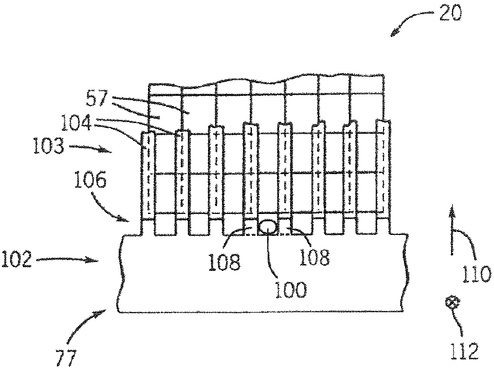
"The present invention is about a new CT detector and a method of manufacturing it. The detector includes a scintillator module with an indexing pin that engages a recess between teeth of a comb. This allows for precise alignment of collimating elements of a collimator assembly. The detector also includes a scintillator and a comb with teeth that align the collimator elements. The detector and collimator are quickly and repeat-ably associated. The invention also includes a CT system with a rotatable gantry and a detector array including scintillator modules with indexing pins and collimator plates that align with the teeth of a comb. The method of manufacturing involves positioning an at least one locator between the teeth of the comb and the scintillator array. The technical effects of the invention include improved accuracy and repeatability in CT detection."

Problems solved by technology

Generally, cross-talk is sought to be reduced as cross-talk leads to artifact presence in the final reconstructed CT image and contributes to poor spatial resolution.
This alignment of the plurality of cells of the scintillator array and the plates of the collimator can be a time consuming a labor intensive process.
Further, the physical placement or alignment of the collimator to the scintillator array is particularly susceptible to misalignment stack-up.
That is, one of the scintillator-collimator assemblies, if unaligned, can detrimentally effect the alignment of adjacent assemblies.
Further, such assemblies require adjusting several detectors when only one of the detectors is misaligned.

Method used


Image

  • Self-aligning scintillator-collimator assembly
  • Self-aligning scintillator-collimator assembly
  • Self-aligning scintillator-collimator assembly

Examples


Embodiment Construction

[0025]The operating environment of the present invention is described with respect to a four-slice computed tomography (CT) system. However, it will be appreciated by those skilled in the art that the present invention is equally applicable for use with single-slice or other multi-slice configurations. Moreover, the present invention will be described with respect to the detection and conversion of x-rays. However, one skilled in the art will further appreciate that the present invention is equally applicable for the detection and conversion of other high frequency electromagnetic energy. The present invention will be described with respect to a “third generation” CT scanner, but is equally applicable with other CT systems.

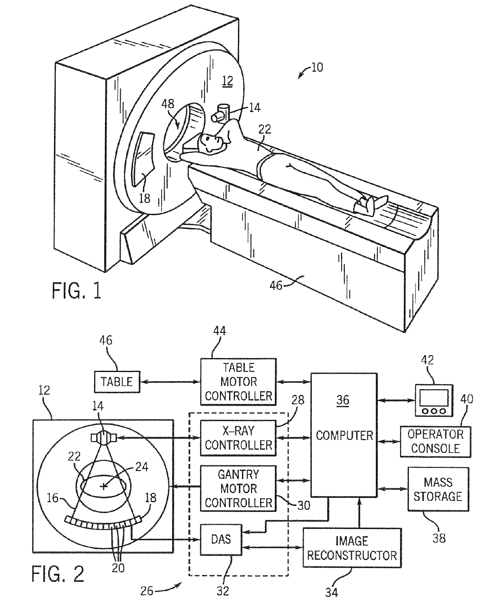
[0026]Referring to FIGS. 1 and 2, a computed tomography (CT) imaging system 10 is shown as including a gantry 12 representative of a “third generation” CT scanner. Gantry 12 has an x-ray source 14 that projects a beam of x-rays 16 toward a detector array 18 on the...


PUM


Abstract

The present invention is directed to scintillator module for a CT detector as well as an apparatus and method of manufacturing the same. The scintillator module is comprised of a scintillator array having a plurality of scintillators aligned in parallel with respect to one another. A collimator assembly includes a comb having a number of teeth and a plurality of collimator plates positioned proximate to the scintillator array. The scintillator array includes at least one indexing pin extending therefrom. The indexing pin engages the comb and is constructed to improve alignment of the scintillator array relative to the collimator plates.

Description

CROSS-REFERENCE TO RELATED APPLICATION[0001]This application claims the benefit of U.S. provisional application Ser. No. 60 / 481,722, filed Nov. 29, 2003.BACKGROUND OF THE INVENTION[0002]The present invention relates generally to diagnostic imaging and, more particularly, to a self-aligning scintillator-collimator assembly and method of manufacturing same.[0003]Typically, in computed tomography (CT) imaging systems, an x-ray source emits a fan-shaped beam toward a subject or object, such as a patient or a piece of luggage. Hereinafter, the terms “subject” and “object” shall include anything capable of being imaged. The beam, after being attenuated by the subject, impinges upon an array of radiation detectors. The intensity of the attenuated beam radiation received at the detector array is typically dependent upon the attenuation of the x-ray beam by the subject. Each detector element of the detector array produces a separate electrical signal indicative of the attenuated beam receive...

Claims


Application Information

Patent Timeline
Patent Type & Authority Patents(United States)
IPC IPC(8): H05G1/64G21K1/02G01T7/00A61B6/03G01T1/164G01T1/20
CPCA61B6/032H01L27/14658G01T1/1648A61B6/4035
Inventor YASUNAGA, TAKASHIGRAVES, BRIANSCHWEINERT, GERHARDT E.
Owner GENERAL ELECTRIC CO
Learn More