
System for spatially adjustable excitation of leadless miniature marker

a technology of leadless miniature markers and excitation systems, which is applied in the field of system for excitation of resonating miniature marker assemblies, can solve the problems of reducing the excitation energy reducing the excitation efficiency of the source coil, so as to achieve high energized

Inactive Publication Date: 2007-02-13
VARIAN MEDICAL SYSTEMS
View PDF107 Cites 84 Cited by
  • Summary
  • Abstract
  • Description
  • Claims
  • Application Information

AI Technical Summary

Benefits of technology

[0014]Another embodiment includes a marker system with a switching network coupled to an energy storage device. A plurality of excitation coils are independently coupled to the switching network. Each of the excitation coils has a coil axis that is non-concentric with the coil axis of the other excitation coils. The excitation coils are configured to simultaneously receive from the switching network alternating electrical signals at a selected phase to generate a magnetic field from the respective coil. The switching network is manipulatable to independently change the phase for each excitation coil. The magnetic fields from the excitation coils are configured to combine with each other to form a modifiable excitation field having selected spatial characteristics for excitation of the leadless marker assembly. The spatially adjustable excitation field of this embodiment effectively avoids blind spots in the excitation of single axis marker assemblies and therefore allows the marker assemblies to be in any orientation relative to the pulsed source generator coil assembly and still be highly energized upon activation of the excitation source coils.

Problems solved by technology

The process of distinguishing a weak marker signal from the strong continuous excitation signal, while maintaining sufficient accuracy and repeatability for determining the marker's location, has proven to be very difficult.
The required levels of magnetic excitation for the markers in the above patents are relatively low such that the excitation energy in the source coil is substantially consumed after each pulse due to the pulse circuitry resistive losses.
The amplitude of the pulsed excitation signal required for these applications is relatively low since either the resonator circuit to be located is of a large size, the volume in which the resonator must be located is relatively small, or the accuracy requirements locating the resonator are quite low.
Accordingly, the existing systems are not suitable for use in many situations wherein highly accurate determinations of the marker's location in three-dimensional space is required.
The existing systems may also not be suitable for use with efficient, high energy systems for energizing the marker assemblies so as to provide a sufficient marker signal for use in determining the location of the marker in three-dimensional space relative to remote sensors.
Providing the switchable damping circuits in series with the antennas increases the power dissipation of the device during pulse delivery due to added damping circuit switch resistance in the antenna current path.
The amplitude of the pulsed excitation signal required for these applications is relatively low since either the resonator circuit to be located is of a large size, the volume in which the resonator must be located is relatively small, or the accuracy requirements locating the resonator are quite low.

Method used


Image

  • System for spatially adjustable excitation of leadless miniature marker
  • System for spatially adjustable excitation of leadless miniature marker
  • System for spatially adjustable excitation of leadless miniature marker

Examples


Embodiment Construction

[0034]In the following description, certain specific details are set forth in order to provide a thorough understanding of various embodiments of the invention. However, one skilled in the art will understand that the invention may be practiced without these details. In other instances, well-known structures associated with magnetic excitation systems, resonating markers, and activators have not been shown or described in detail to avoid unnecessarily obscuring the description of the embodiments of the invention.

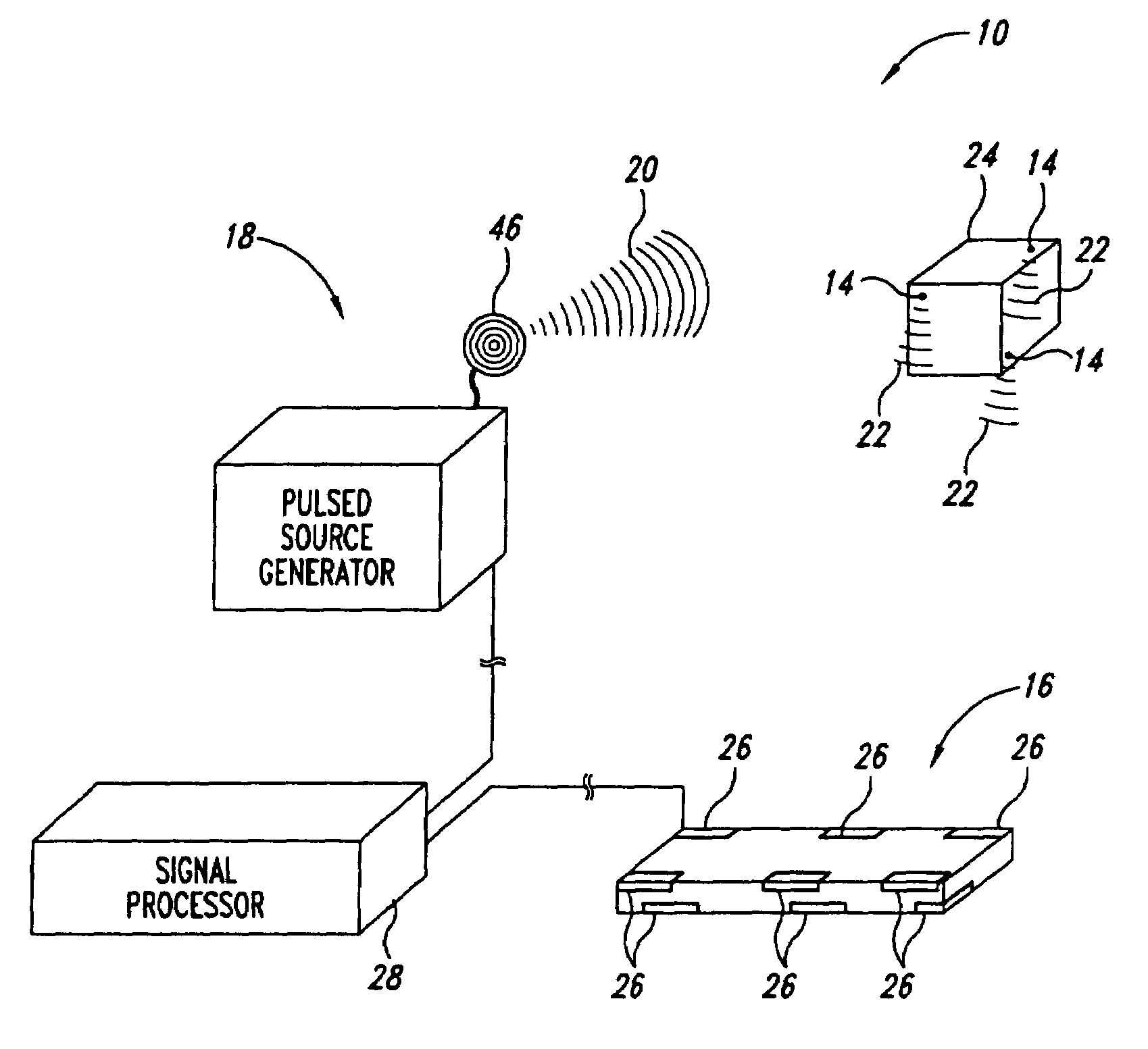
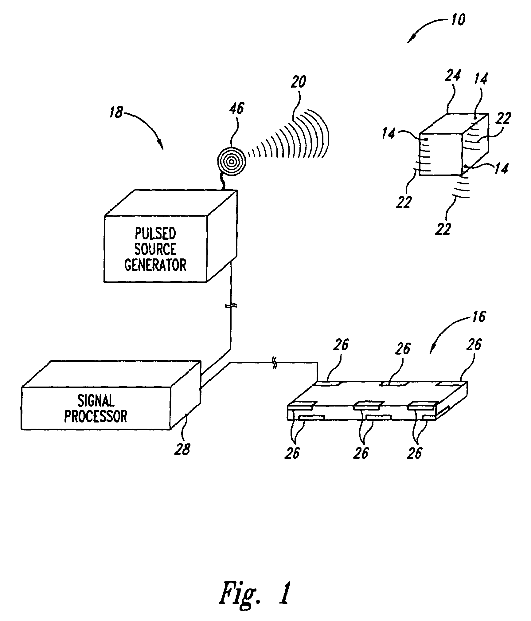
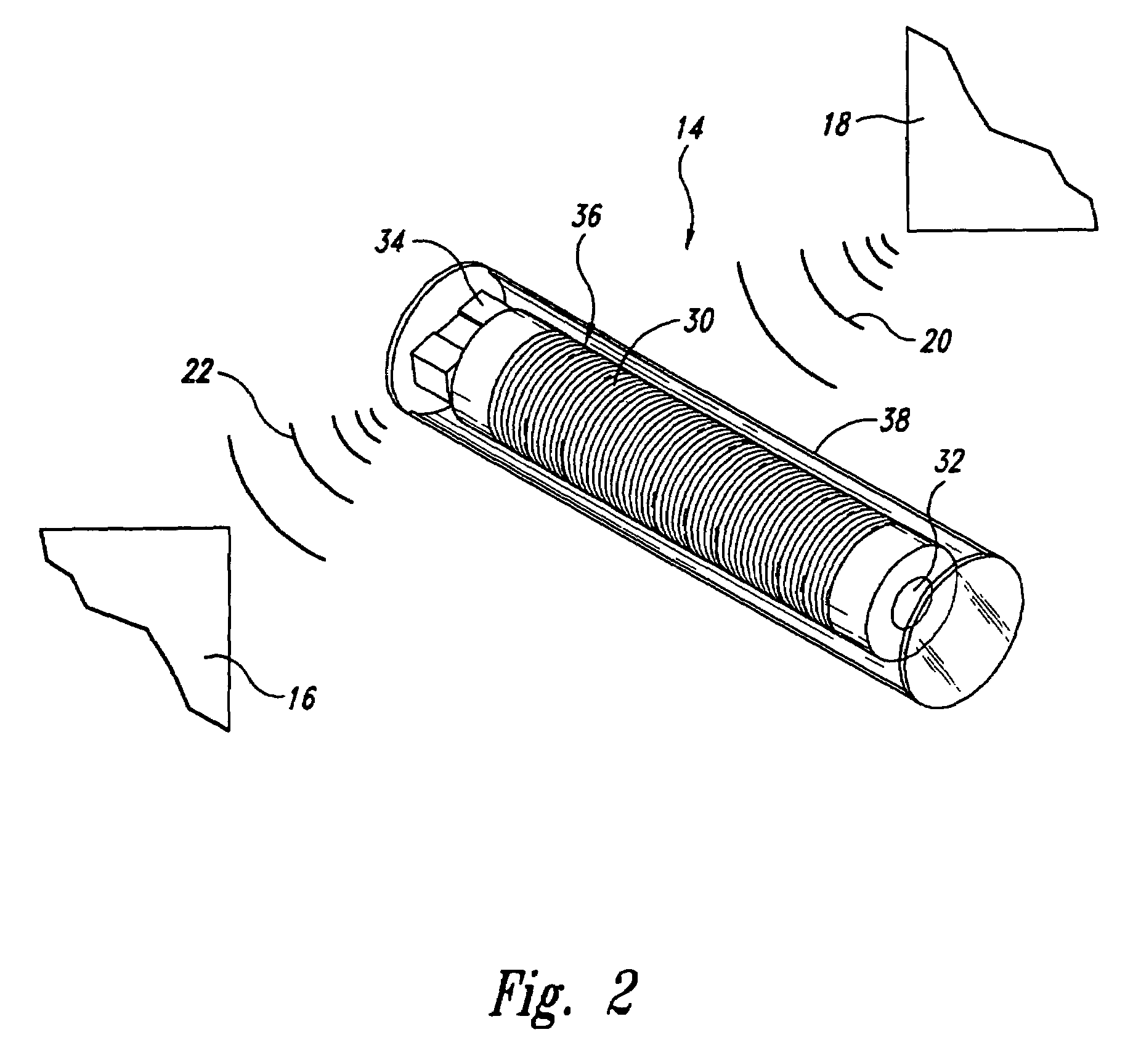
[0035]FIGS. 1–16 illustrate a system and components for generating an excitation signal for activating a resonating marker assembly and locating the marker in three-dimensional space in accordance with embodiments of the present invention. Several of the components described below with reference to FIGS. 1–16 can also be used in systems for performing methods in accordance with aspects of the present invention. Therefore, like reference numbers refer to like components and f...


PUM


Abstract

A system for generating a magnetic field for excitation of a leadless marker assembly. The system of at least one embodiment includes a source generator that generates a plurality of alternating electrical signals each having an independently adjustable phase. A plurality of excitation coils are configured to simultaneously receive a respective one of the alternating electrical signals at a selected phase to generate a magnetic field. The phase of the alternating electrical signal for each excitation coil is independently adjustable relative to the phase of the alternating electrical signal for the other excitation coils so as to adjust the magnetic field from the respective coil. The magnetic fields from the excitation coils combine to form a spatially adjustable excitation field for excitation of the remote leadless marker assembly.

Description

CROSS REFERENCE TO RELATED APPLICATIONS[0001]This application is a continuation of U.S. patent application Ser. No. 10 / 213,980, titled SYSTEM FOR SPATIALLY ADJUSTABLE EXCITATION OF LEADLESS MINIATURE MARKER, filed Aug. 7, 2002, which issued on Nov. 23, 2004 as U.S. Pat. No. 6,822,570, which is a continuation-in-part of U.S. application Ser. No. 10 / 044,056, tilted SYSTEM FOR EXCITATION LEADLESS MINIATURE MARKER, filed Jan. 11, 2002, which issued on Jan. 4, 2005 as U.S. Pat. No. 6,838,990, which is a continuation-in-part of U.S. patent application Ser. No. 10 / 027,675, titled SYSTEM FOR EXCITATION OF LEADLESS MINIATURE MARKER, filed Dec. 20, 2001, which issued on Nov. 2, 2004 as U.S. Pat. No. 6,812,842.TECHNICAL FIELD[0002]This invention relates to systems for activating miniature markers, and more particularly to systems for excitation of resonating miniature marker assemblies for use in locating the markers in three-dimensional space.BACKGROUND OF THE INVENTION[0003]Systems have been...

Claims


Application Information

Patent Timeline
Patent Type & Authority Patents(United States)
IPC IPC(8): G08B13/14G01B7/00A61B19/00A61N5/10G01S5/16G08B13/24
CPCA61B5/06A61B19/52A61B19/5244H01Q7/08G08B13/2414A61B2017/00154A61B2017/00411A61B2019/5458A61B2019/5475A61N5/1049A61N2005/1051A61B2019/5251A61B5/062A61B34/20A61B90/36A61B2034/2051A61B2090/3958A61B2090/3975
Inventor DIMMER, STEVEN C.WRIGHT, J. NELSONMAYO, WILLIAM T.
Owner VARIAN MEDICAL SYSTEMS
Learn More