Device control system

a control system and device technology, applied in the field of device control systems, can solve the problems of low utility, cumbersome recovery operation, and low power saving efficiency, and achieve the effects of improving power saving efficiency, simple circuit, and simple control operation

Inactive Publication Date: 2007-02-13
FUJIFILM BUSINESS INNOVATION CORP
View PDF16 Cites 6 Cited by
  • Summary
  • Abstract
  • Description
  • Claims
  • Application Information

AI Technical Summary

Benefits of technology

[0009]The present invention has been made to solve the above-described problems of the conventional device control system, and therefore, has an object to provide a device control system capable of recovering a hung-up condition of a USB interface by executing a simple control operation, while employing a simple circuit, and also capable of improving a power saving efficiency.

Problems solved by technology

Also, when the power supply of the USB interface is cut out, since a communication from the host appliance to the device appliance cannot be performed, the power supply of the USB interface must be maintained under ON state even while the device appliance is controlled in a power saving mode and thus a power supply of a partial circuit portion thereof is cut out.
As a result, a power saving efficiency becomes lower.
As previously described, in the conventional device control system, the recovery operation for such a case that the USB interface happens to hang up becomes cumbersome and the utility thereof is low.
For instance, in the case that a built-in type electronic appliance employs such a USB interface, when a power supply is cut out, there are some possibilities that a power supply of an entire system must be interrupted, resulting in low utility.
Also, since the supply of electric power to the USB interface cannot be stopped in order to accept the communications even while the device appliance is controlled in the power saving mode, the power saving efficiency becomes low.

Method used


Image

  • Device control system
  • Device control system

Examples


Embodiment Construction

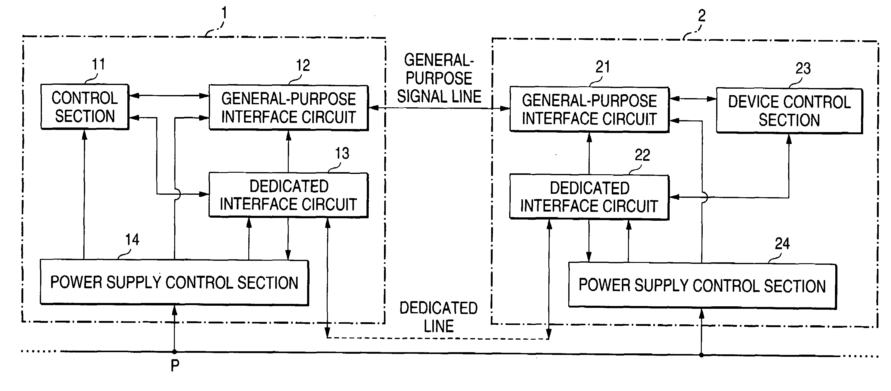
[0019]Referring now to drawings, an embodiment of the present invention will be described. As indicated in FIG. 1, a device control system according to an embodiment of the present invention includes a host appliance 1 and a device appliance 2. Electric power is supplied via a power supply line “P” to these appliances 1 and 2. The host appliance 1 contains a control section 11, a general-purpose interface circuit 12, a dedicated (exclusively-used) interface circuit 13, and a power supply control section 14. Also, the device appliance 2 contains a general-purpose interface circuit 21, a dedicated (exclusively-used) interface circuit 22, a device control section 23, and a power supply control section 24. In this case, both the power supply control section 14 of the host appliance 1 and the power supply control section 24 of the device appliance 2 correspond to a unit for performing a power supply control of the invention.

[0020]The control section 11 of the host appliance 1 transmits a...


PUM


Abstract

While a general-purpose interface circuit and another general-purpose interface circuit are provided so as to transmit/receive data between a host appliance and a device appliance, when the general-purpose interface of the device appliance happens to hang up, a control section transmits a reset signal via a dedicated interface circuit. When a dedicated interface circuit provided on the side of the device appliance receives this reset signal and then outputs this received reset signal to the general-purpose interface circuit, the general-purpose interface circuit is reinitiated.

Description

[0001]The present disclosure relates to the subject matter contained in Japanese Patent Application No. 2001-327450 filed on Oct. 25, 2001, which is incorporated herein by reference in its entirety.BACKGROUND OF THE INVENTION[0002]1. Field of the Invention[0003]The present invention is related to a device control system for controlling a device appliance by transmitting / receiving a signal between a host appliance and the device appliance.[0004]2. Description of the Related Art[0005]Recently, there are many cases that the USB (Universal Serial Bus) standard has been employed as serial interfaces utilized in data communications and so on. This USB standard is employed so as to transmit / receive communication data between, for instance, a personal computer and a modem. Also, for example, in the case that a FAX apparatus (facsimile machine) functioning as a built-in type device appliance which is built in a copy machine is connected to a control apparatus of the copy machine functioning ...

Claims


Application Information

Patent Timeline
Patent Type & Authority Patents(United States)
IPC IPC(8): G08B9/00G06F1/24G05B19/042G06F13/00H04L12/28
CPCG05B19/0428G05B2219/24125
Inventor EDOGAWA, KAZUYASUGITA, HIROSHISONOBE, KENICHITAKAHASHI, HIROTAHOSHINO, TSUTOMUKANEKO, TOMOKAZU
Owner FUJIFILM BUSINESS INNOVATION CORP
Why Eureka
Try Eureka