
Method and apparatus using polarisation optical time domain reflectometry for security applications

a technology of optical time domain and reflectometry, which is applied in the direction of material analysis, measurement devices, and fluid detection at leakage points, etc., can solve the problems of large optical power loss and inability to identify the location of disturbances in the detection zon

Inactive Publication Date: 2007-02-06
SENSTAR CORP
View PDF10 Cites 34 Cited by
  • Summary
  • Abstract
  • Description
  • Claims
  • Application Information

AI Technical Summary

Benefits of technology

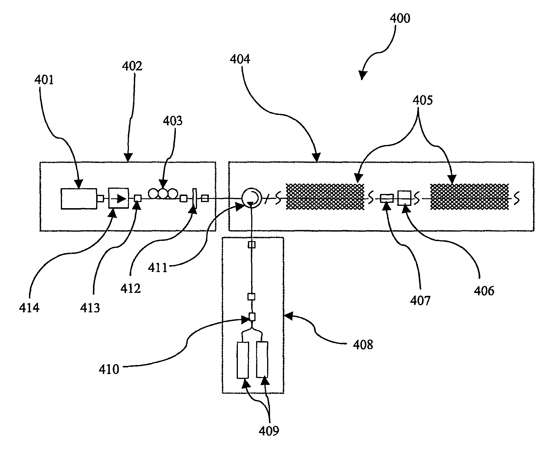
The POTDR system enables accurate detection and location of disturbances along optical fibers with high precision, demonstrated in field tests up to 2 km with ±2 m accuracy and less than 0.5 second update rates, improving response times and reducing false alarms by varying alarm thresholds based on fiber length.

Problems solved by technology

Both of these techniques result in a large loss of optical power.
The current prior art sensors as briefly described above are all equally unable to identify the location of disturbances within the detection zone, especially at any specific location along the length of the fiber.

Method used


Image

  • Method and apparatus using polarisation optical time domain reflectometry for security applications
  • Method and apparatus using polarisation optical time domain reflectometry for security applications
  • Method and apparatus using polarisation optical time domain reflectometry for security applications

Examples


Embodiment Construction

[0021]The invention will be described for the purposes of illustration only in connection with certain embodiments; however, it is to be understood that other objects and advantages of the present invention will be made apparent by the following description of the drawings according to the present invention. While a preferred embodiment is disclosed, this is not intended to be limiting. Rather, the general principles set forth herein are considered to be merely illustrative of the scope of the present invention and it is to be further understood that numerous changes may be made without straying from the scope of the present invention.

[0022]The present invention improves upon the prior art that cannot identify the location of disturbances within the detection zone. The present invention is an outcome of an investigation into the use of fiber optic time domain reflectometer techniques to locate targets along the length of an optical fiber for security applications. In fiber optic tim...


PUM

PropertyMeasurementUnit
FWHMaaaaaaaaaa
FWHMaaaaaaaaaa
center wavelengthsaaaaaaaaaa

Abstract

A preferred apparatus and method is presented in which a distributed fiber optic sensor is used in order to detect a disturbance along its length. A pulse of polarized light is launched into an optical fiber; as the pulse propagates along the optical fiber, it continuously loses a small portion of its energy due to Rayleigh backscatter. The Rayleigh backscattered light is analyzed using a polarization sensitive element such as a fiber polarizer. The dynamics of the time dependence of the polarization analyzed backscattered light is used to ascertain if there has been a disturbance along the length of the optical fiber. This technique can be used for applications in areas such as fiber optic telecommunications, perimeter security, fire detection, and pipelines.

Description

BACKGROUND OF THE INVENTION[0001]1. Field of the Invention[0002]The present invention relates to a method and apparatus for detecting a disturbance along a length of optical fiber. More specifically, the present invention uses Polarization Optical Time Domain Reflectometry (POTDR) to ascertain if there has been a disturbance along the length of the optical fiber. This technique can be used for security applications in areas such as, but not limited to, fiber optic perimeter security, telecommunications, fire detection, and pipelines.[0003]2. Description of Prior Art[0004]A number of intrusion detection systems are commercially produced. Many of these systems have detection zone lengths from tens of meters up to several kilometers. Oftentimes, these systems will only identify merely whether or not an intrusion has occurred within the detection zone. It would be advantageous with an intrusion detection system to obtain the specific location of the disturbance within the detection zone...

Claims


Application Information

Patent Timeline
Patent Type & Authority Patents(United States)
IPC IPC(8): G01N21/00G01M3/18G01N21/21
CPCG01N21/21G01M3/18G01S7/499
Inventor HARAN, FRANCIS M.
Owner SENSTAR CORP
Learn More