
Wire-coil packaging drum with improved bottom assembly

a technology of bottom assembly and wire coil, which is applied in the field of container or drum, can solve the problems of complicated drum assembly process, inability to adjust the elastic cord, and high cost and labor intensity

Inactive Publication Date: 2007-02-06
GREIF PACKAGING
View PDF10 Cites 23 Cited by
  • Summary
  • Abstract
  • Description
  • Claims
  • Application Information

AI Technical Summary

Benefits of technology

"The present invention provides an improved bottom assembly for a drum that includes a bottom heading with a hole and an anchoring member mounted to the bottom heading. The anchoring member is made of plastic and has a flange and a resilient member that is inserted into the hole of the bottom heading. The anchoring member is secured to the bottom heading using a tie. The invention also replaces the conventional elastic cord with an elastic loop member that is secured to the anchoring member using a tie. The elastic loop member can be adjusted in length to adjust the compressive force on the wire coil in the drum. The technical effects of the invention include improved stability and secure anchoring of the wire coil, adjustable compressive force, and improved protection of the wire coil during transportation."

Problems solved by technology

This is a costly and labor-intensive operation.
Further, this operation is performed before attaching the bottom heading to the drum body, thereby complicating the drum assembly process.
Other disadvantages stem from the fact that the elastic cord is not adjustable.
As a result of this, the compressive force applied to the wire coil by the elastic cord cannot be adjusted.
Further, the cord is limited to use only with drums within a certain height range.
This is inconvenient and leaves open the possibility that an assembly worker will mistakenly select an elastic cord of an incorrect length, so that the wire coil is not properly secured by the hold-down system.
However, the attachment of the strap to the core still constitutes a costly and labor intensive operation.
In addition, the Cooper patent does not address the problems stemming from lack of adjustability of the elastic cord.

Method used


Image

  • Wire-coil packaging drum with improved bottom assembly
  • Wire-coil packaging drum with improved bottom assembly
  • Wire-coil packaging drum with improved bottom assembly

Examples


Embodiment Construction

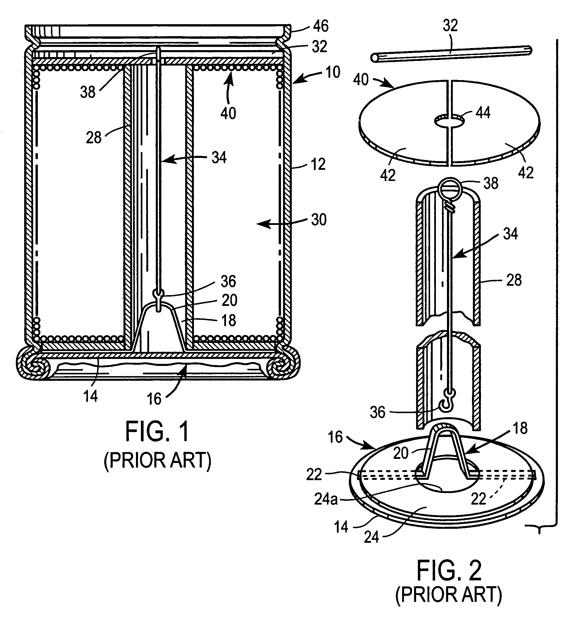
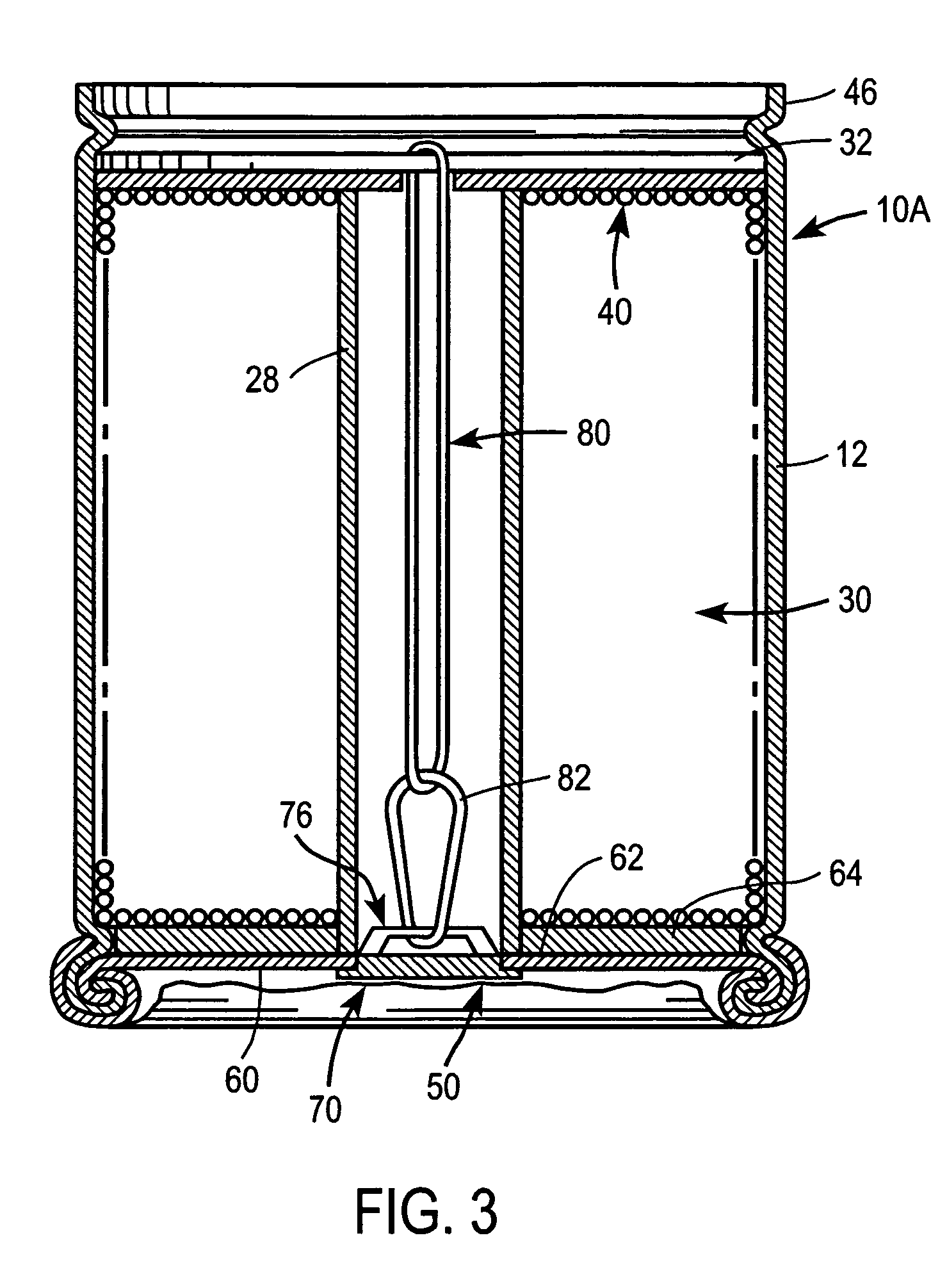
[0025]FIG. 3 shows a wire-coil packaging drum 10A incorporating an improved bottom assembly and hold-down system according to the present invention. The structural differences between the drums shown in FIGS. 1 and 3 reside principally in the construction of the bottom assembly 50 and hold-down system. The following description will therefore focus on those portions of the drum.

[0026]The bottom assembly 50 comprises a drum bottom heading 60 having a central hole 62. The hole 62 is preferably circular, although it will be appreciated that other shapes may be suitable. An annular disk 64 may be mounted onto bottom heading 60 to provide strength, if desired, as in the conventional structure. An anchoring member 70 is mounted to the bottom heading 60 in cooperation with hole 62 such that an anchoring portion 76 of anchoring member 70 is disposed for anchoring a hold-down system for a wire coil 30, as will be explained shortly.

[0027]Referring additionally to FIGS. 4–6, anchoring member 7...


PUM


Abstract

A game machine (2, 200) which includes a playing field (6, 301) traversed by objects, such as balls (320). The playing field can have plural drop zones (381–383) which can be selected by the player using deflectors (108–110) that control where the balls are launched. Detectors (22, 392) indicate scoring positions assumed by the balls. A payline display (28, 335) displays scored events. A symbol selector is included to select symbols which are variably assigned to the scoring positions and displayed on displays (20, 397). The balls score symbols which can be displayed in the payline display and affect winning or bonus play. Game machine (200) includes traditional slot machine reels which works in conjunction therewith.

Description

CROSS-REFERENCE TO RELATED APPLICATION[0001]This application claims the benefit of U.S. Application No. 60 / 126,338 filed Mar. 26, 1999.BACKGROUND OF THE INVENTION[0002]This invention relates to containers or drums used for packaging wire coils, and more specifically, to an improved bottom assembly for such containers or drums.[0003]FIGS. 1 and 2 of the accompanying drawings illustrate a conventional wire-coil packaging drum 10 as disclosed in U.S. Pat. No. 5,105,943 to Lesko et al. (incorporated herein by reference). The drum 10, which is ordinarily made of pasteboard, includes a cylindrical drum body 12 and a bottom assembly 16 designed to anchor a hold-down system (to be described below) for a wire coil 30 received in the drum. The hold-down system serves as a dunnage for the wire coil during transport—specifically by applying a compressive force to the top of the coil to reduce shifting of the coil due to vibration and other movement of the drum.[0004]The drum bottom assembly 16 ...

Claims


Application Information

Patent Timeline
Patent Type & Authority Patents(United States)
IPC IPC(8): B65D85/66B65D85/04B65D85/676
CPCB65D85/676B65D85/04
Inventor COON, THOMAS D.ADAMS, RANDALL
Owner GREIF PACKAGING
Learn More