
Control method for electronically controlled thermostat

a control method and thermostat technology, applied in the direction of machine/engine, measurement device, cooling apparatus, etc., can solve the problems of large power distribution amount variation, inability to implement constant water temperature control of electronically controlled thermostats through general pid control, and time-consuming and laborious, etc., to achieve suitably and efficiently implement the cooling water temperature, without the risk of overshooting, undershooting, hunting

Active Publication Date: 2007-02-06
NIPPON THERMOSTAT CO LTD
View PDF7 Cites 6 Cited by
  • Summary
  • Abstract
  • Description
  • Claims
  • Application Information

AI Technical Summary

Benefits of technology

[0016]The present invention was conceived in view of this situation, an object thereof being to provide a control method for an electronically controlled thermostat that makes it possible to dispense with the inconvenience of the above-mentioned problems of the prior art and to implement high cooling-water temperature controllability, improved fuel consumption, and an improvement of the heater function and so forth with high accuracy and at low cost.
[0022]The present invention is capable of implementing the cooling water temperature suitably and efficiently in accordance with the engine load in a state where the automobile is operating. The present invention is superior in terms of its responsiveness and cooling-water temperature stability, is capable of suitably controlling the cooling water temperature to the required temperature without the risk of overshooting, undershooting, hunting, or the like, and is able to produce improved fuel consumption more reliably and over substantially the whole range of the operative states.

Problems solved by technology

Further, in the case of an electronically controlled thermostat in which a heater element is installed in a temperature sensor as mentioned earlier, after the power distribution control for the heater element has distributed power to the heater element installed in the temperature sensor, the response time until the valve opens and feedback to the water temperature occurs poses a problem.
Further, a larger power-distribution amount variation cannot be applied to the heater element because the power distribution amount is an amount proportional to the water temperature gradient.
Therefore, for the reasons listed above, it is difficult to implement constant water temperature control of the electronically controlled thermostat by means of general PID control.
However, in the case of a conventional WAX-type thermostat control method, the difference in temperature between the thermostat open-valve temperature and fan-operating temperature is large (10° C. or more, for example).
This is because the fan operating temperature has the characteristic of being set at the temperature at which the thermostat is fully open and the fan operating temperature is fixed at a temperature at which the engine does not break down, and it is therefore difficult to set the thermostat fully-open temperature boundlessly at a high value.

Method used


Image

  • Control method for electronically controlled thermostat
  • Control method for electronically controlled thermostat
  • Control method for electronically controlled thermostat

Examples


Embodiment Construction

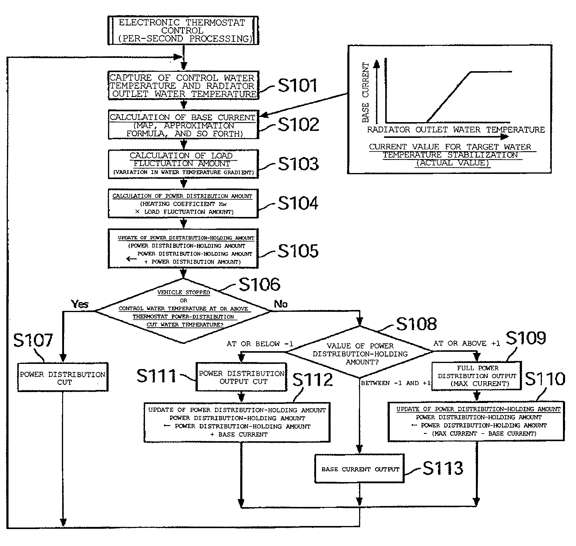
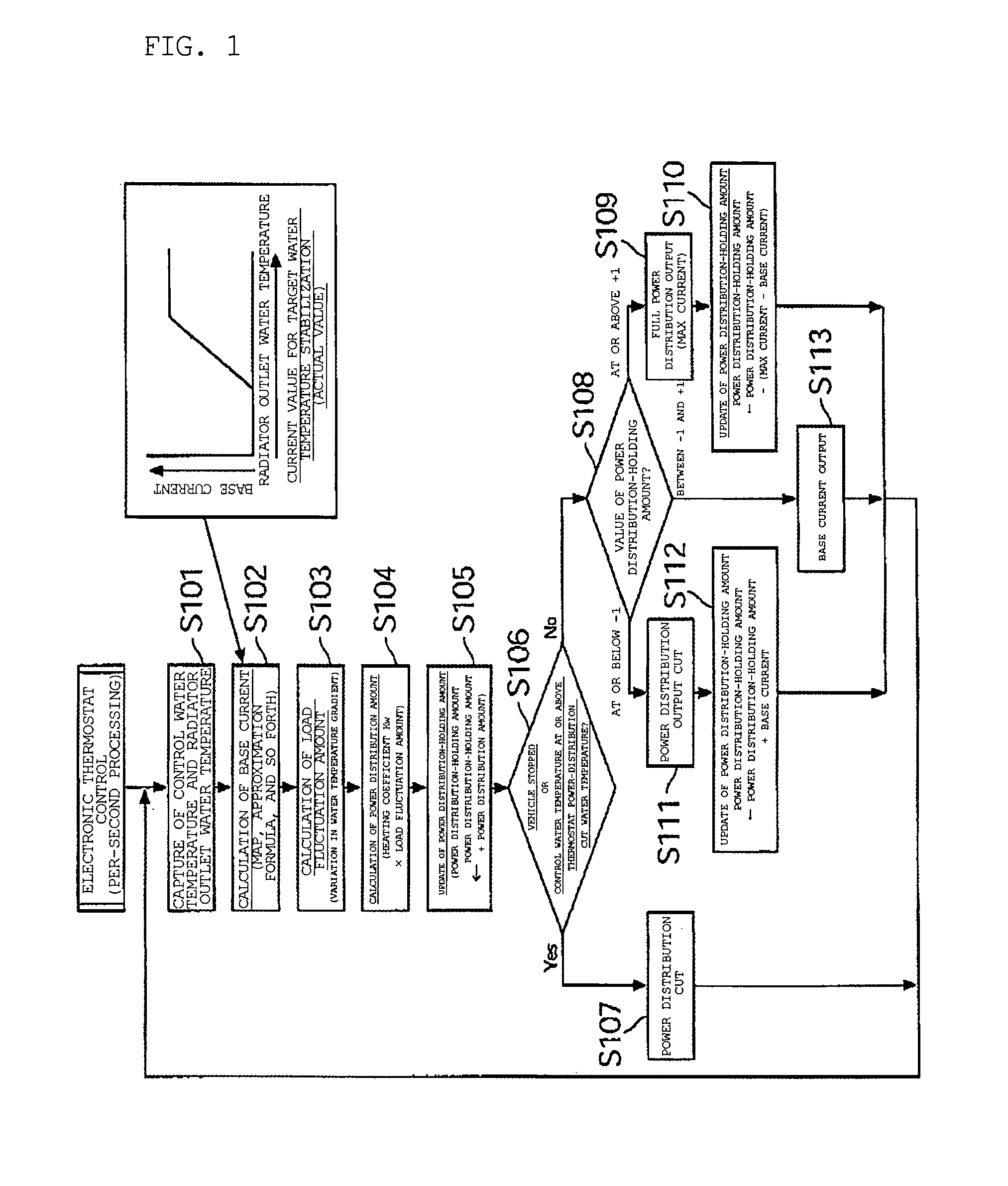
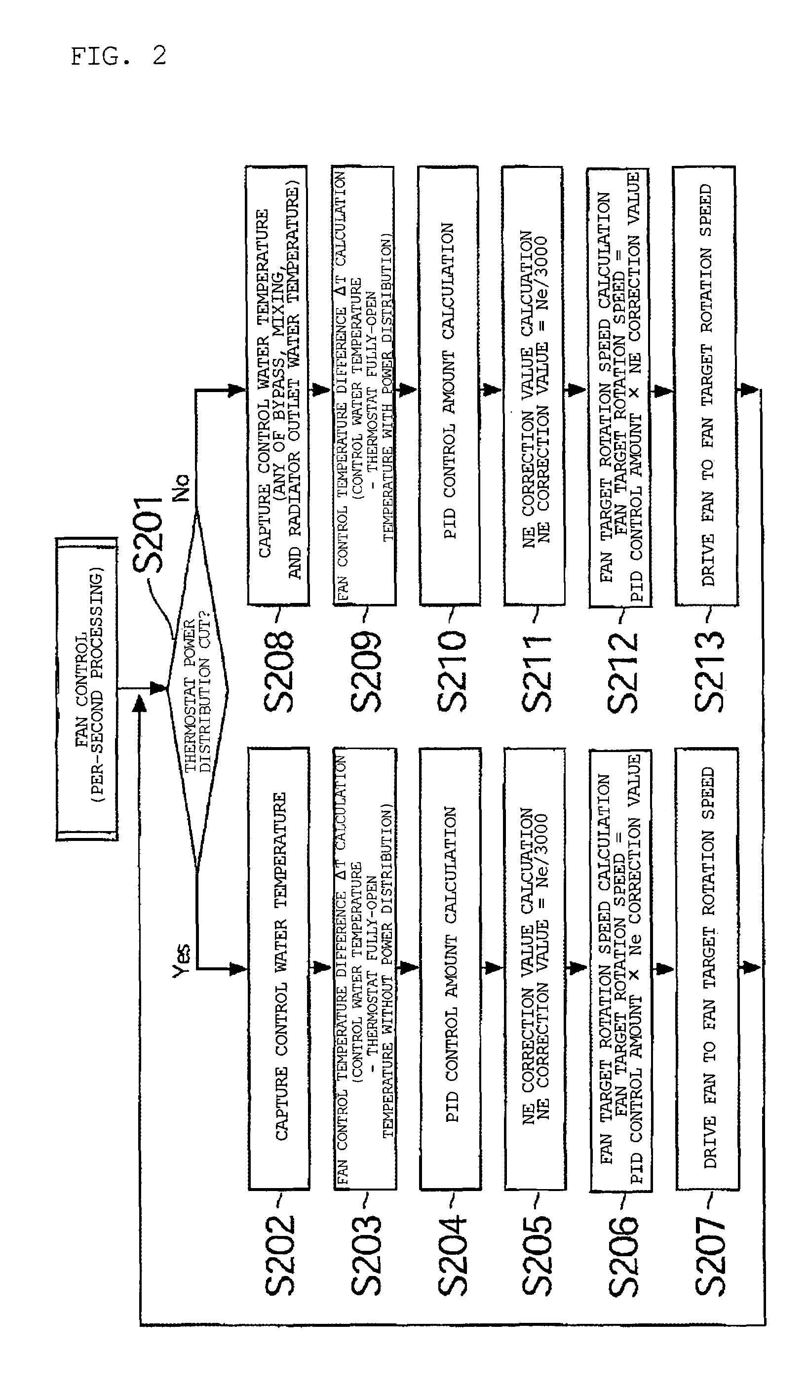
[0026]FIGS. 1 to 3 show one embodiment of the control method for an electronically controlled thermostat according to the present invention.

[0027]These figures will be first described below based on FIG. 3, which provides an overall outline of an automobile-engine cooling-water temperature control system that comprises an electronically controlled thermostat.

[0028]In FIG. 3, 1 is an automobile engine, which is an internal combustion engine constituted by a cylinder block 1a and a cylinder head 1b, in which a fluid path denoted by the arrow c is formed in the cylinder block 1a and cylinder head 1b of the engine 1.

[0029]2 is a heat exchanger, that is, a radiator. A fluid passage 2c is formed, as is common knowledge, in the radiator 2, and a cooling water inlet 2a and a cooling water outlet 2b of the radiator 2 are connected to a cooling water path 3 respectively that allows cooling water to be circulated between the radiator 2 and the engine 1.

[0030]This cooling water path 3 is consti...


PUM


Abstract

A control method for an electronically controlled thermostat includes that an actuator is used for cooling-water control of an internal combustion engine and the actuator is capable of optionally varying the valve-opening ratio. An engine control unit computes a target temperature by means of various engine parameters and distributes the power distribution amount required to operate the actuator so that the cooling water temperature reaches the target temperature. The power distribution amount distributed to the actuator is determined by monitoring only the actual water temperature of the cooling water.

Description

BACKGROUND OF THE INVENTION[0001]1. Field of the Invention[0002]The present invention relates to a control method for an electronically controlled thermostat capable of optionally varying the valve-opening ratio by installing a heater element in a temperature sensor, for example, in a cooling-water temperature control system for an internal combustion engine (hereinafter referred to as ‘engine’) that is employed in an automobile or the like.[0003]2. Description of the Related Art[0004]A water-cooling-type cooling device that employs a radiator is generally used in order to cool an automobile engine. Further, conventionally, with the objective of improving the fuel consumption of the automobile, this type of cooling device employs a control valve, such as a thermostat, for example, which adjusts the amount of cooling water circulated to the radiator to permit control of the temperature of the cooling water introduced to the engine. Known examples of such thermostats include those tha...

Claims


Application Information

Patent Timeline
IPC IPC(8): F01P7/14F01P5/04F01P7/04F01P11/16F01P7/16
CPCF01P7/048F01P7/167F01P2007/146F01P2070/04F01P2023/08F01P2025/32F01P2023/00
Inventor SANO, MITSUHIRO
Owner NIPPON THERMOSTAT CO LTD
Learn More