
Estimating signal strength measurements in a telecommunications system

a telecommunications system and signal strength technology, applied in the direction of transmission monitoring, modulation, electrical equipment, etc., can solve the problems of insufficient optimal tuning of the receiver, inability to carry out inter-frequency or inter-rat (radio access technology) measurements, and increase the average power consumption

Inactive Publication Date: 2007-01-30
TELEFON AB LM ERICSSON (PUBL)
View PDF23 Cites 13 Cited by
  • Summary
  • Abstract
  • Description
  • Claims
  • Application Information

AI Technical Summary

Benefits of technology

The present invention provides a method for estimating signal measurements in a telecommunications system by performing measurements in two or more co-located cells and using the difference value between the measurements to estimate the second measurement for the second cell. This method allows for more accurate signal strength measurements and improved communication between cells in the system.

Problems solved by technology

However, there are certain factors which act against this general desire to reduce power levels.
For example, data compression can be used to transmit a given amount of data in less time, resulting in gaps being created to allow inter-frequency or inter-RAT (Radio Access Technology) measurements to be carried out.
In addition to the peak power being increased during the data compression, the average power also needs to be increased to compensate for the channel estimates that are not being updated during the time gaps, resulting in the receiver not being optimally tuned after the time gaps.
While increased inter-frequency and inter-RAT measurements typically have the disadvantage of increasing the average power consumption when using real time services with requirements of low delays, for example speech, they also have a degrading effect in that they reduce the available channelization-codes.
This type of solution suffers from the disadvantage that each neighbouring cell is treated equally as if they were adjacent neighbours using different antennas covering different, but to some extent overlapping, geographical areas.

Method used


Image

  • Estimating signal strength measurements in a telecommunications system
  • Estimating signal strength measurements in a telecommunications system
  • Estimating signal strength measurements in a telecommunications system

Examples


Embodiment Construction

[0017]In a WCDMA based radio access network, several cells may be co-located using different frequencies. The network will have information that a particular cell, say Cell A, is co-located with one or more other cells, say Cell B.

[0018]A mobile station positioned in a given location is able to make signal measurements on common pilot channels (CPICHs) transmitted from a serving cell and any co-located cells.

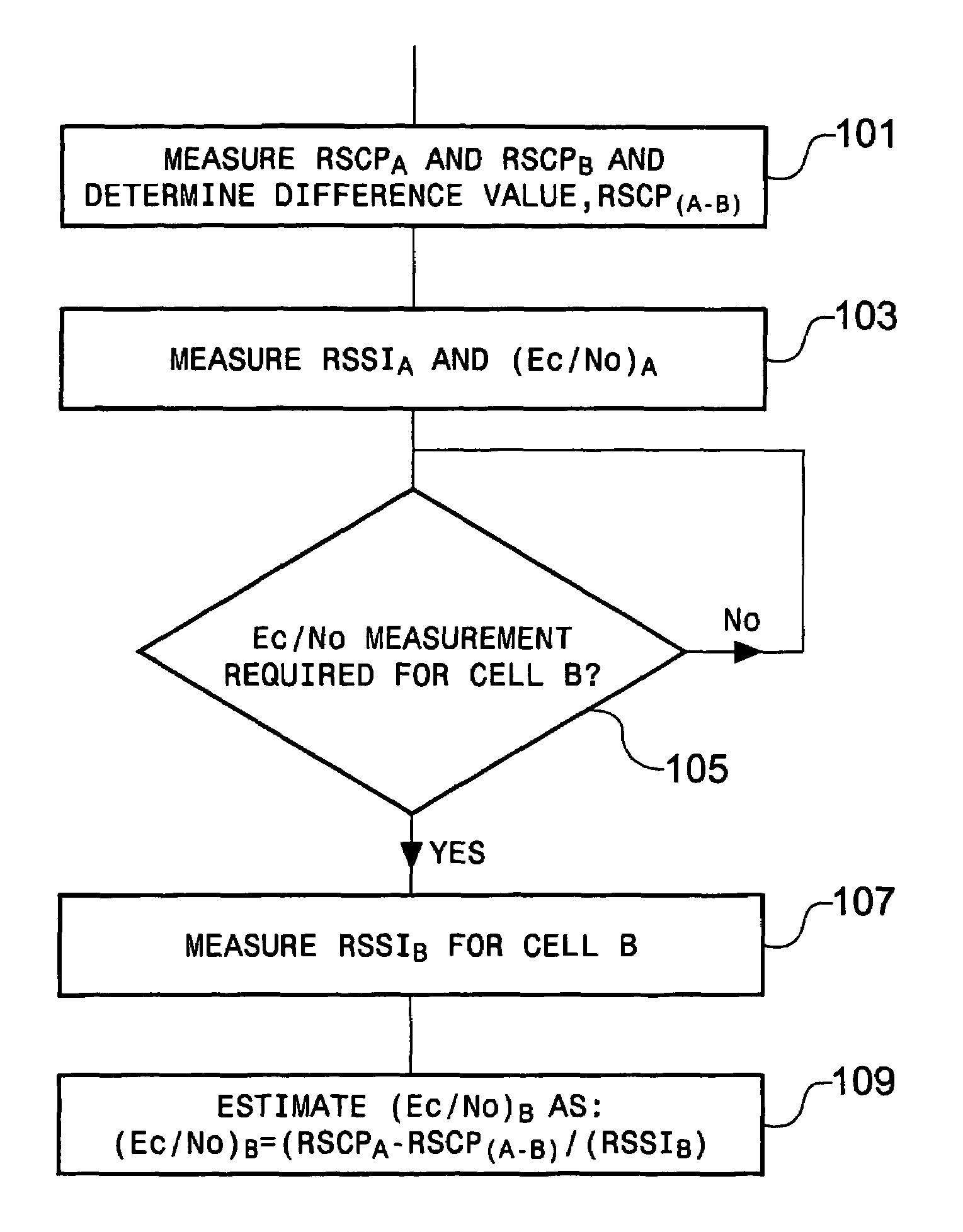
[0019]FIG. 1 shows the steps involved in estimating a measurement according to a first aspect of the present invention.

[0020]In step 1, the network instructs a mobile station to perform a predetermined measurement in Cell A and in co-located Cell B, for example a received signal code power (RSCP) measurement, hereinafter referred to as RSCPA and RSCPB, respectively. These measurements are reported by the mobile station to the network.

[0021]The network determines the difference between the two signals (RSCPA−B) which is stored for future reference, step 3.

[0022]Once the differenc...


PUM


Abstract

The number of measurements being performed in a telecommunications system can be reduced by performing a predetermined measurement in Cell A and in co-located Cell B, step 1, for example a received signal code power (RSCP) measurement. The difference between the two signals is determined, and stored for future reference, step 3. Once the difference value has been established, the mobile station no longer needs to perform measurements on both Cell A and Cell B. Instead, if a subsequent measurement is made on Cell A, step 5, the network can estimate the measurement for Cell B based on the difference signal previously determined, step 7.

Description

FIELD OF THE INVENTION[0001]The present invention relates to performing measurements in a telecommunications system, and in particular, to estimating measurements in a telecommunications system, thereby reducing the number of measurements being performed.BACKGROUND OF THE INVENTION[0002]In a telecommunications system, for example a wideband CDMA system (WCDMA), there is always a desire to communicate using the least amount of power. Therefore, all transmissions should ideally be performed at the lowest possible power level, while still maintaining an acceptable quality level.[0003]However, there are certain factors which act against this general desire to reduce power levels. Certain communication techniques have an inherent need for the power levels to be increased, both in the mobile station and the network.[0004]For example, data compression can be used to transmit a given amount of data in less time, resulting in gaps being created to allow inter-frequency or inter-RAT (Radio Ac...

Claims


Application Information

Patent Timeline
Patent Type & Authority Patents(United States)
IPC IPC(8): H04Q7/20H04B17/00H04W72/54
CPCH04B17/327H04W72/08H04W72/54
Inventor MULLER, WALTER
Owner TELEFON AB LM ERICSSON (PUBL)
Learn More