
Circuit breaker and terminal cover

a terminal cover and circuit breaker technology, applied in the direction of switch terminal/connection, circuit breaker contact, switch circuit breaker, etc., can solve the problem of difficult detachment of the terminal cover at a site, and achieve the effect of improving operability, convenient attachment and detachment, and improving operability

Active Publication Date: 2007-01-30
FUJI ELECTRIC FA COMPONENTS & SYST CO LTD
View PDF9 Cites 11 Cited by
  • Summary
  • Abstract
  • Description
  • Claims
  • Application Information

AI Technical Summary

Benefits of technology

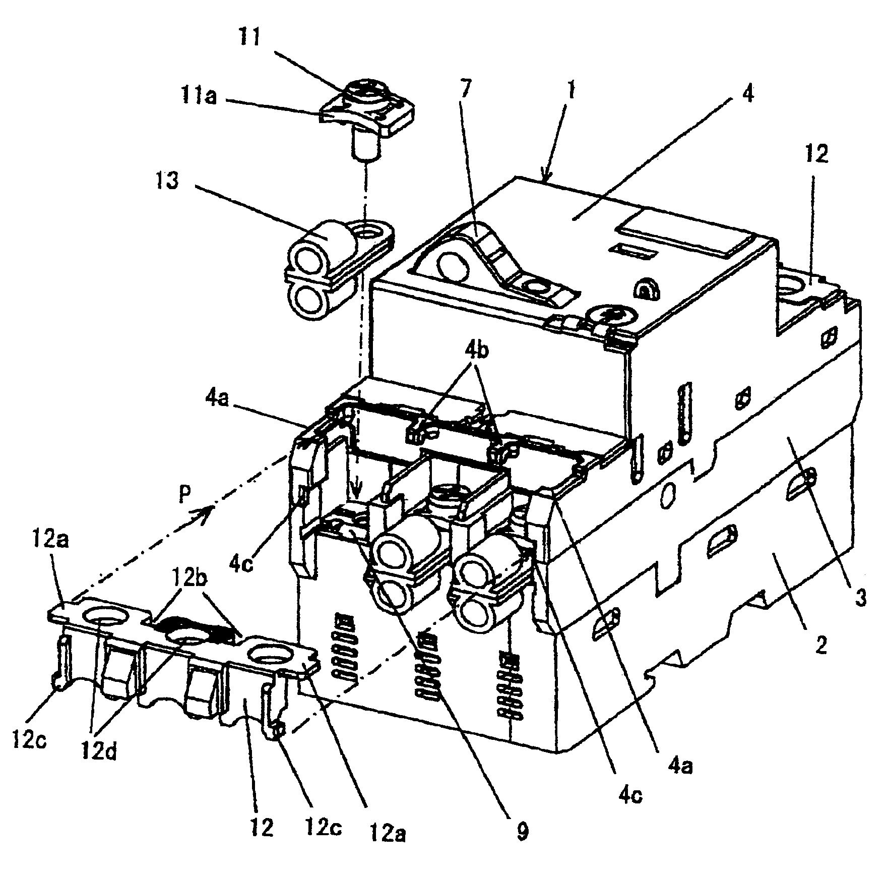
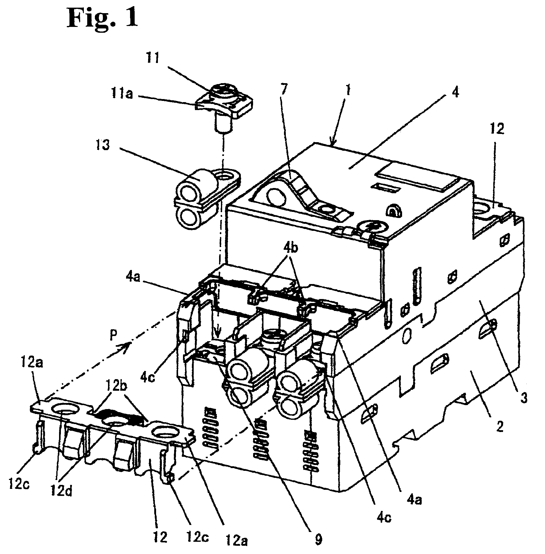
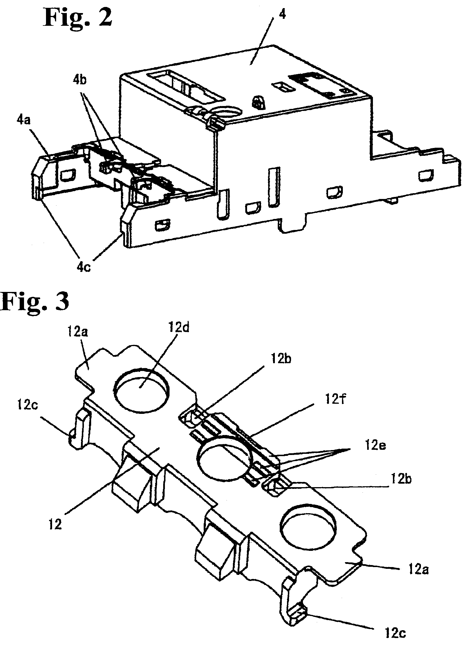
The invention relates to a circuit breaker with a terminal cover that can be easily attached and detached from the main body case. The terminal cover is secured at the front and rear ends of the main body case using a snap-fit coupling. The snap-fit coupling includes a terminal cover attaching surface on the main body case, a claw-shaped snap-fit fastener on the terminal cover, and a rear end edge of the terminal cover with an engaging groove hole for fitting the claw of the fastener. The terminal cover can be easily detached by pressing the release operation surface on the upper surface of the terminal cover and pulling it out. The invention also provides a terminal cover that can be easily attached to the main body case using a flat-tip screwdriver and a support unit to prevent the terminal cover from coming out upwardly upon a current interruption. The terminal cover is formed of a long cover extending in a forward direction of the main body case and surrounding whole press terminals tightened by a screw to each terminal. The cover has inter-phase partitions for isolating the terminals in each phase from others and slits and holes for voltage detection. The invention improves operability and prevents electric shock accidents.

Problems solved by technology

Accordingly, it is difficult to detach the terminal cover at a site where a plurality of circuit breakers is mounted in line in a panel such as a switchboard.

Method used


Image

  • Circuit breaker and terminal cover
  • Circuit breaker and terminal cover
  • Circuit breaker and terminal cover

Examples


Embodiment Construction

[0025]Hereunder, embodiments of the invention will be explained with reference to the attached drawings.

[0026]FIG. 1 to FIG. 5 show an embodiment corresponding to the first to sixth aspects of the invention. In FIGS. 4A and 4B showing the whole structure of a circuit breaker, a main body case 1 is a molded resin case with a three-way split structure formed of a lower case 2, an intermediate case 3, and a cover 4. In the main body case 1, there are incorporated principal parts such as a current interrupting unit 5, a switching mechanism 6, a switching operation handle 7, and an over-current tripping device 8.

[0027]At one end and the other end of the main body case 1, power supply side terminals 9 and load side terminals 10 of a main circuit are taken out, respectively. A terminal screw 11 is screwed into each of the terminals together with a washer ha to form a terminal section for an external wiring. Furthermore, in correspondence with the positions of the terminals on each of the p...


PUM


Abstract

A circuit breaker includes terminals with screws on a power supply side and a load side disposed at a front end section and a rear end section of a main body case containing a current interrupting unit and a switching mechanism. A terminal cover is detachably attached onto the main body case at a position corresponding to the terminals on at least one of the power supply side and the load side. A terminal cover attaching surface is formed on an upper surface on the power supply side and / or the load side of the main body case. The terminal cover is inserted while sliding on the attaching surface from a front end, so that the terminal cover is attached to the main body case with a snap-fit coupling unit at an assembling position.

Description

BACKGROUND OF THE INVENTION AND RELATED ART STATEMENT[0001]The present invention relates to a terminal cover of a circuit breaker such as a molded-case circuit breaker and an earth leakage breaker, and to an attaching structure of the cover.[0002]In a circuit breaker, a terminal cover is provided for covering a terminal (a threaded terminal) on each of a power source side at one end and a load side at the other end of a main body case (a molded resin case) Accordingly, a live-part is not exposed, thereby preventing an electric shock accident. Patent Reference 1 has disclosed a circuit breaker in which a terminal cover is detachably attached onto a main body case, so that a press ring terminal is secured to a terminal by tightening a screw.[0003]In the structure disclosed in Patent Reference 1, the terminal cover has an engaging hole in each of right and left side walls thereof. When the terminal cover is pushed into the main body case of the circuit breaker from above a terminal sec...

Claims


Application Information

Patent Timeline
Patent Type & Authority Patents(United States)
IPC IPC(8): H01H13/04H01H19/04H01H73/20H01H9/02H01H71/08H01H71/54H01H73/00H01H73/04H01H73/06
CPCH01H9/0264H01H73/045H01H71/54
Inventor KAWATA, HISAOKUBOYAMA, KATSUNORINAGAHIRO, ISAMU
Owner FUJI ELECTRIC FA COMPONENTS & SYST CO LTD
Learn More