
Water irrigation system with moisture gauge and method of controlling irrigation

a technology of water irrigation system and moisture gauge, which is applied in the field of water irrigation system, can solve the problems that the amount of moisture in the collector may alter the frequency of the resonant circuit, and achieve the effect of reducing the amount of moisture in the collector

Inactive Publication Date: 2007-01-23
JAMES JOLLY CLARK
View PDF26 Cites 34 Cited by
  • Summary
  • Abstract
  • Description
  • Claims
  • Application Information

AI Technical Summary

Benefits of technology

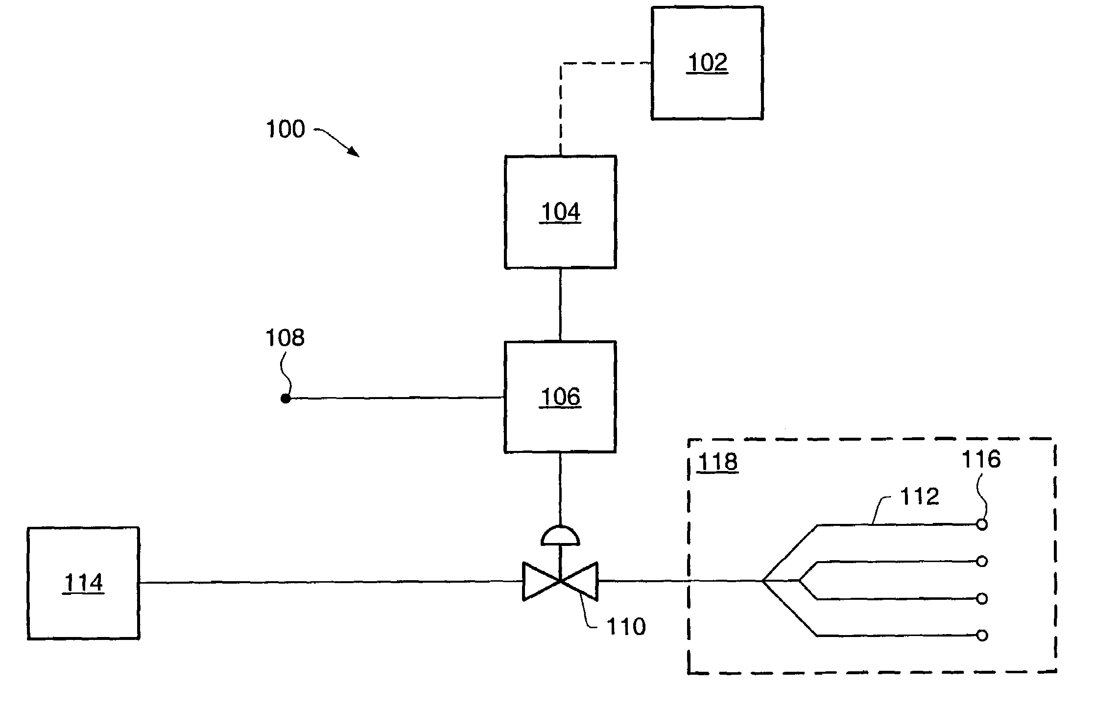
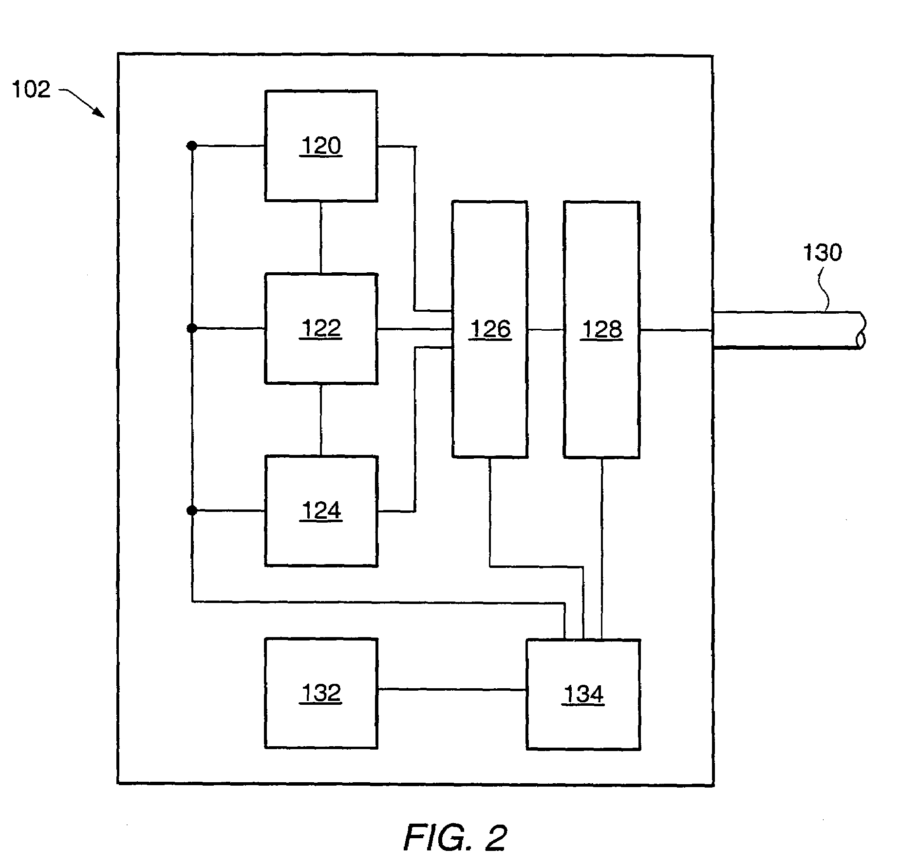
[0015]In an embodiment, a water irrigation system may include a computer system and a sensing unit. The sensing unit may be elevated at least 2 meters above the computer system. The sensing unit may include a solar panel. The solar panel may use sunlight to produce electricity and provide at least a portion of the electricity to the sensing unit. The sensing unit may assess climatological conditions. The sensing unit may communicate wirelessly with the computer system. The sensing unit may provide output that is a function of the assessed climatological conditions to the computer system. In some embodiments, the computer system may control irrigation of a zone to be irrigated at least partially based on the output of the sensing unit.
[0016]In an embodiment, a method of controlling irrigation may include receiving sunlight with a solar panel, using the received sunlight to produce electricity, and using at least a portion of the electricity to assess climatological conditions. The method may further include transmitting output that is a function of the assessed climatological conditions...

Problems solved by technology

A change in an amount of moisture in the collector may alter a frequency of the resonant circuit.

Method used


Image

  • Water irrigation system with moisture gauge and method of controlling irrigation
  • Water irrigation system with moisture gauge and method of controlling irrigation
  • Water irrigation system with moisture gauge and method of controlling irrigation

Examples


Embodiment Construction

[0031]A water irrigation system may be designed to control irrigation of a zone to be irrigated to promote water conservation while maintaining a desired appearance and allowing enough growth to maintain healthy vegetation. As used herein, to “control” irrigation generally means to initiate, terminate, inhibit, adjust a duration and / or frequency of, regulate, or otherwise effect irrigation. As used herein, a “zone to be irrigated” generally refers to a volume that receives or is intended to receive water from a water irrigation system during an irrigation cycle. A lower boundary of the volume is the surface that receives or is intended to receive water from the water irrigation system. An upper boundary of the volume is determined by an average height that water travels from the irrigation devices during irrigation. As used herein, an “irrigation cycle” generally includes initiation of irrigation with a water irrigation system, delivery of water to a zone to be irrigated, and termin...


PUM


Abstract

A water irrigation system may include a computer system, a sensing unit, an irrigation controller, and / or a water delivery system. The sensing unit may include a moisture gauge. The moisture gauge may include a capacitor coupled to a collector. The sensing unit may assess an amount of moisture in the collector and provide output that is a function of the amount of moisture in the collector to the computer system. The computer system may control irrigation of a zone to be irrigated at least partially based on the assessed amount of moisture in the collector. A method of controlling irrigation may include assessing an amount of moisture in a collector near or in a zone to be irrigated and controlling irrigation at least partially based on the assessed amount of moisture in the collector.

Description

BACKGROUND[0001]1. Field of Invention[0002]The present invention generally relates to a water irrigation system. More particularly, the invention relates to a sensing unit that assesses climatological conditions in or near a zone to be irrigated and a computer system that uses the assessed climatological conditions and historical evapotranspiration data to assess an irrigation need of the zone to be irrigated. The computer system may control irrigation to at least meet the irrigation need of the zone to be irrigated.[0003]2. Description of Related Art[0004]Water irrigation systems are used in residential, agricultural, and commercial settings. Some water irrigation systems use historical and / or predictive climatological data (e.g., evapotranspiration data, precipitation data), restrictive data, and / or climatological conditions to adjust irrigation of a zone to be irrigated. Some water irrigation systems include local control and / or remote intelligence from a centralized data source....

Claims


Application Information

Patent Timeline
IPC IPC(8): A01G27/00B05B3/00B05B3/18A01G25/16
CPCA01G25/167
Inventor CLARK, JAMES JOLLYPERKINS, MICHAEL T.SMALL, DAVID
Owner JAMES JOLLY CLARK
Learn More