Optical fiber
a technology of optical fiber and fiber, applied in the field of optical fiber, can solve the problems of increased manufacturing costs, reduced service life, and low cost required for such an application, and achieve the effects of suppressing dispersion, reducing nonlinear effects, and increasing transmission capacity of trunk lines or long-distance lines
- Summary
- Abstract
- Description
- Claims
- Application Information
AI Technical Summary
Benefits of technology
Problems solved by technology
Method used
Image
Examples
example 1
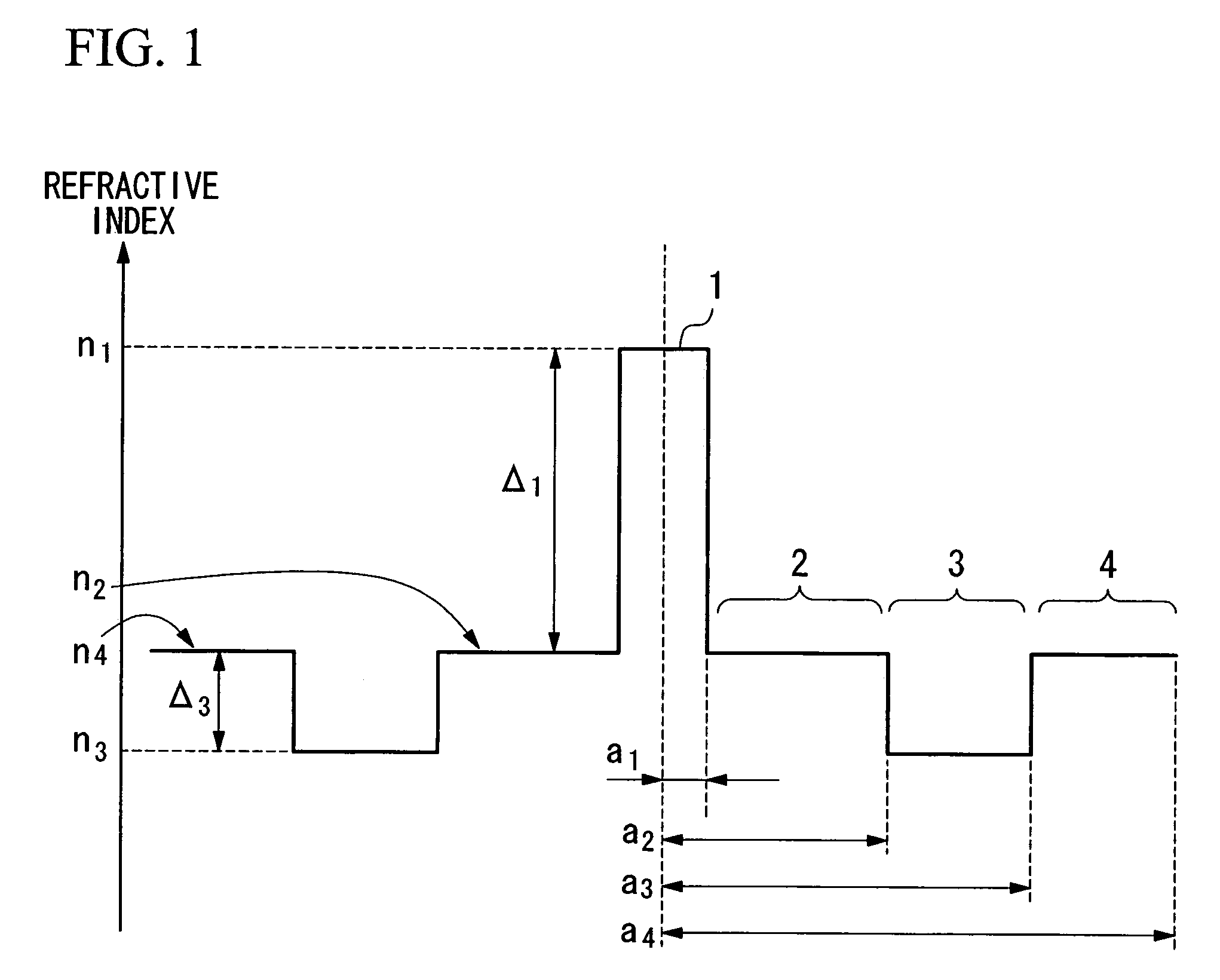
[0096]The refractive index profile of the optical fiber in this example is shown in FIG. 4.
[0097]The optical fiber of this example was manufactured by forming the region labeled as (a) in the figure using the VAD method. Then, after the thus obtained core material using the VAD method was drawn, it was subjected to an outside deposition to form the region (b). After the resulting preform was further drawn, it was subjected to an outside deposition to form the region (c). Upon the formation of the region (b), SiF4 gas was introduced during the process of vitrification, thereby obtaining a refractive index lower than that of silica by addition of F. FIG. 4 is the result of the measurement of the refractive index profiles of the preform obtained by the above-described process using a preform analyzer (brand name: MODEL 2600, manufactured by Kinetics Inc. / York Technology Ltd.). As can be seen from this figure, although the refractive index profile of the optical fiber of this example do...
example 2
[0112]The refractive index profile of the optical fiber in this example is shown in FIG. 5. The optical fiber of this example was manufactured following the same procedure as that of the above-described Example 1. FIG. 5 shows the result of the refractive index profile of the preform measured using the preform analyzer. As can be seen from this figure, although the refractive index profile of the optical fiber of this example does not have a perfect step-shaped shape, it can achieve advantageous effects of the present invention.
[0113]Each parameter of the optical fiber of this example was as follows:
[0114]The radius a1 of the core 1: 3.40 μm
[0115]The radius a2 of the first cladding layer 2: 11.48 μm
[0116]The radius a3 of the second cladding layer 3: 16.45 μm
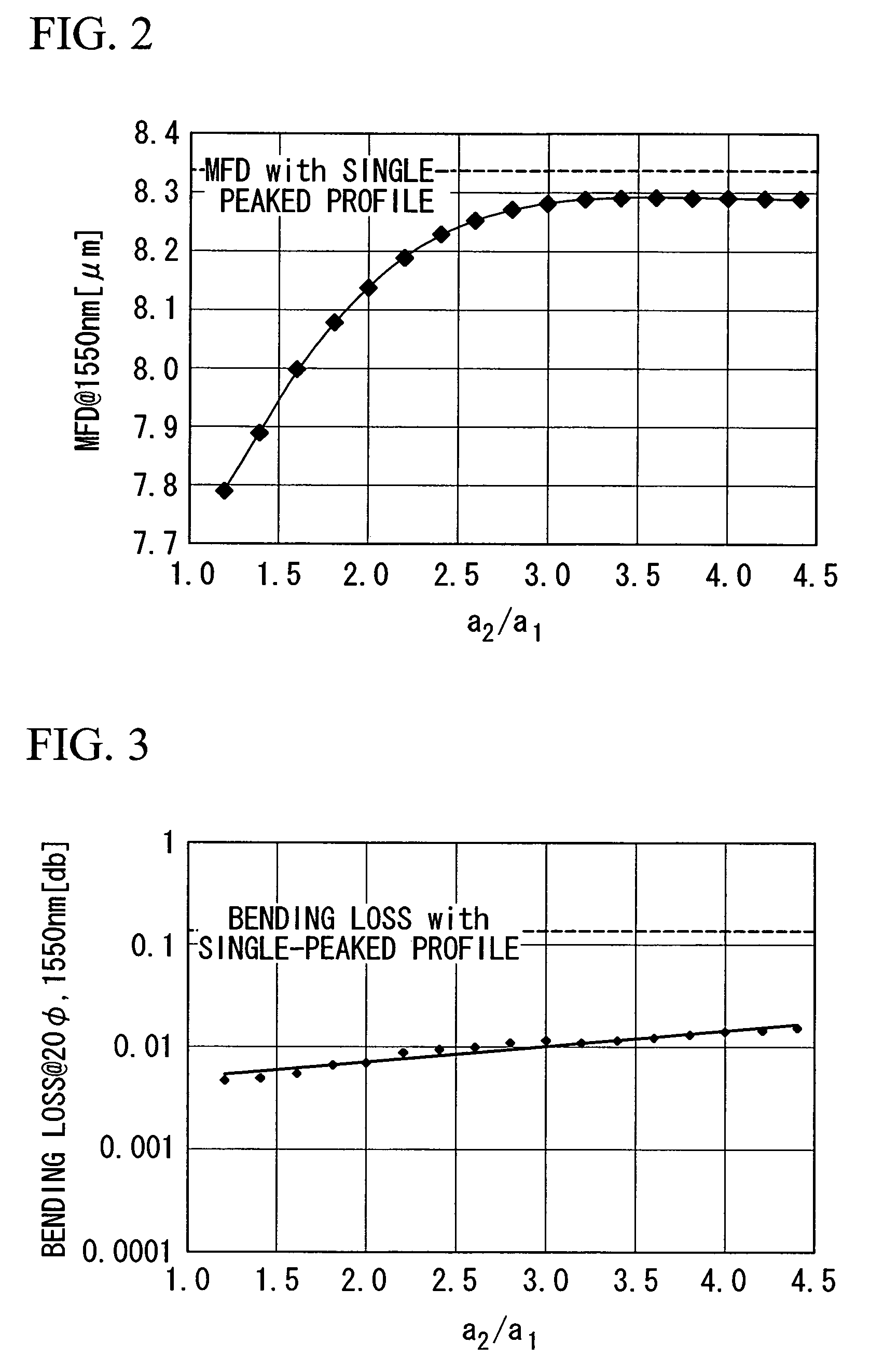
[0117]The ratio a2 / a1 of the radius of the first cladding layer 2 to the radius of the core 1: 3.37
[0118]The outer diameter of the optical fiber: 125 μm
[0119]The refractive index volume (V) of the second cladding layer 3: 55.8%·μ...
example 3
[0126]The refractive index profile of the optical fiber in this example is shown in FIG. 6.
[0127]The optical fiber of this example was manufactured by forming the region labeled as (a) in the figure using the MCVD method. In the figure, the region (b) is the starting silica tube used in the CVD method. The core material obtained by the MCVD method was subjected to an outside deposition to form the region (c). FIG. 6 shows the result of the refractive index profile of the preform measured using the preform analyzer. As can be seen from this figure, although the refractive index profile of the optical fiber of this example also does not have a perfect step-shaped shape, it can achieve advantageous effects of the present invention.
[0128]Each parameter of the optical fiber of this example was as follows:
[0129]The radius a1 of the core 1: 3.12 μm
[0130]The radius a2 of the first cladding layer 2: 10.30 μm
[0131]The radius a2 of the first cladding layer 2: 16.62 μm
[0132]The ratio a2 / a1 of t...
PUM
| Property | Measurement | Unit |
|---|---|---|
| cut-off wavelength | aaaaa | aaaaa |
| diameter | aaaaa | aaaaa |
| diameter | aaaaa | aaaaa |
Abstract
Description
Claims
Application Information
 - R&D
- Intellectual Property
- Life Sciences
- Materials
- Tech Scout
- Unparalleled Data Quality
- Higher Quality Content
- 60% Fewer Hallucinations
Browse by: Latest US Patents, China's latest patents, Technical Efficacy Thesaurus, Application Domain, Technology Topic, Popular Technical Reports.
© 2025 PatSnap. All rights reserved.Legal|Privacy policy|Modern Slavery Act Transparency Statement|Sitemap|About US| Contact US: help@patsnap.com


