
Method and apparatus for detecting structures of interest

a technology of structures and instruments, applied in the field of imaging devices, can solve the problems of inability to produce difficult to locate veins and arteries in many patients, and inability to provide an image of an acceptable quality of the image of the device, etc., to achieve the effect of reducing or eliminating the brightness variation in the imag

Inactive Publication Date: 2007-01-02
GEE JR JAMES W +1
View PDF37 Cites 112 Cited by
  • Summary
  • Abstract
  • Description
  • Claims
  • Application Information

AI Technical Summary

Benefits of technology

"The invention provides a method and device for detecting a structure of interest. The method involves shading the target from ambient light and acquiring multiple raw images, reducing background noise, and then amplifying the images to detect the structure of interest. The device includes an illuminator for shading the target and a camera for acquiring the raw images. The invention can be used in various applications such as in industrial inspection or medical diagnosis."

Problems solved by technology

Veins and arteries in many patients are difficult to find.
Further, unskilled technicians have great difficulty in locating subcutaneous structures even in normal patients.
However, none of these devices provided an instrument that produces an image of an acceptably high enough quality to permit rapid and trouble-free finding of vascular structures in patients.
In particular, many imaging devices have difficulty handling ambient light, which can interfere with image acquisition and image processing.

Method used


Image

  • Method and apparatus for detecting structures of interest
  • Method and apparatus for detecting structures of interest
  • Method and apparatus for detecting structures of interest

Examples


Embodiment Construction

1. System Overview

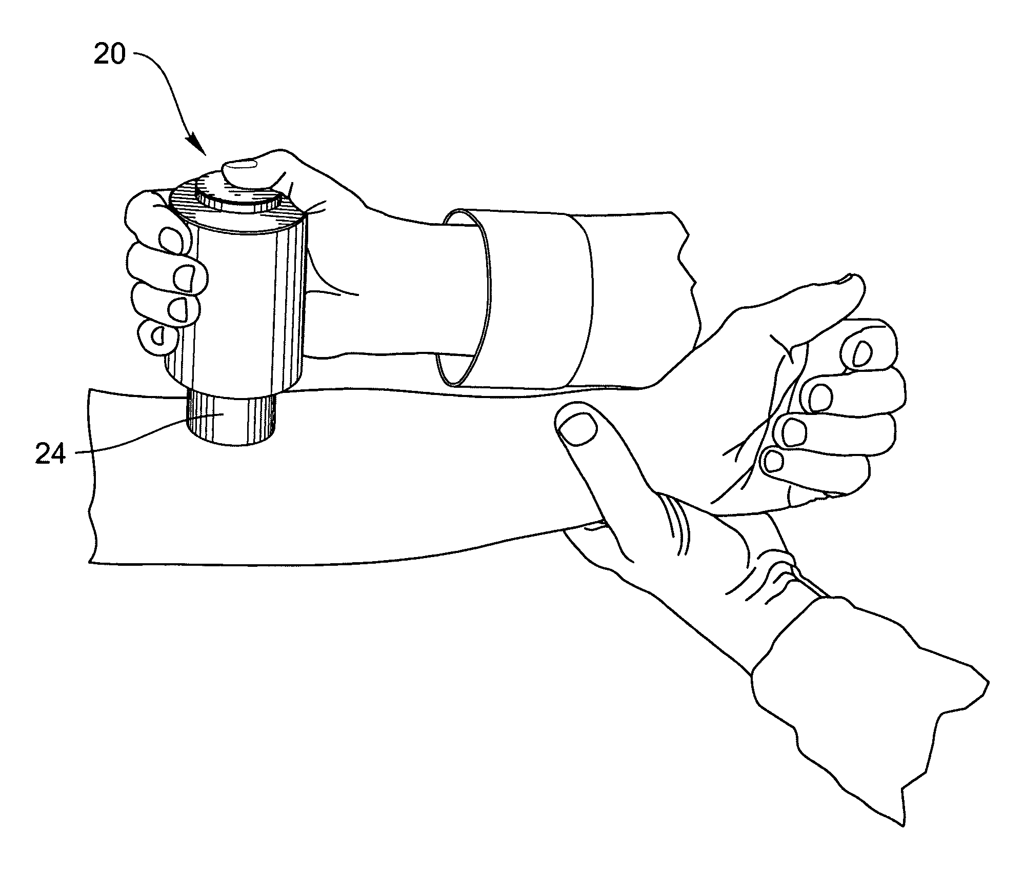
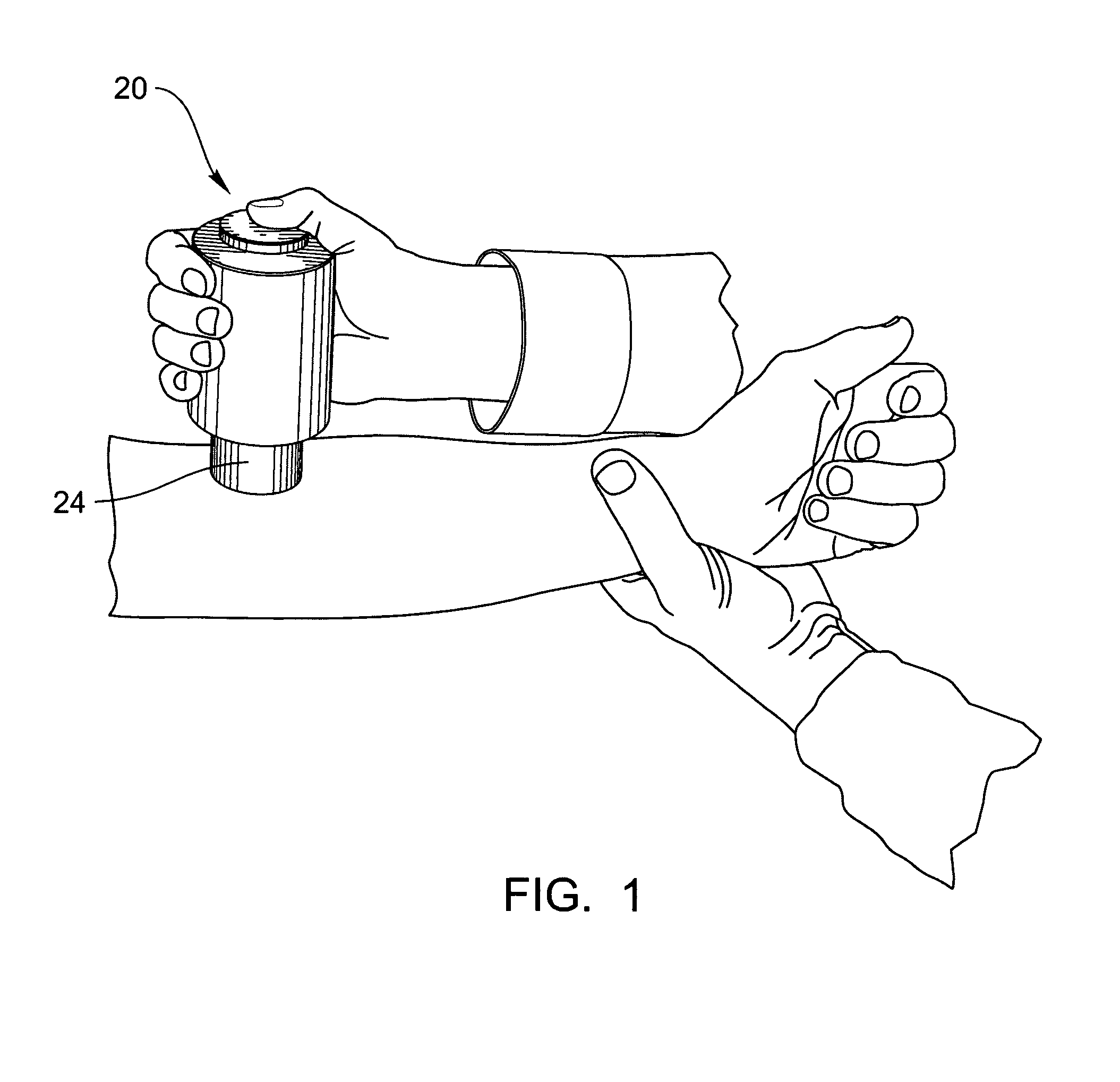
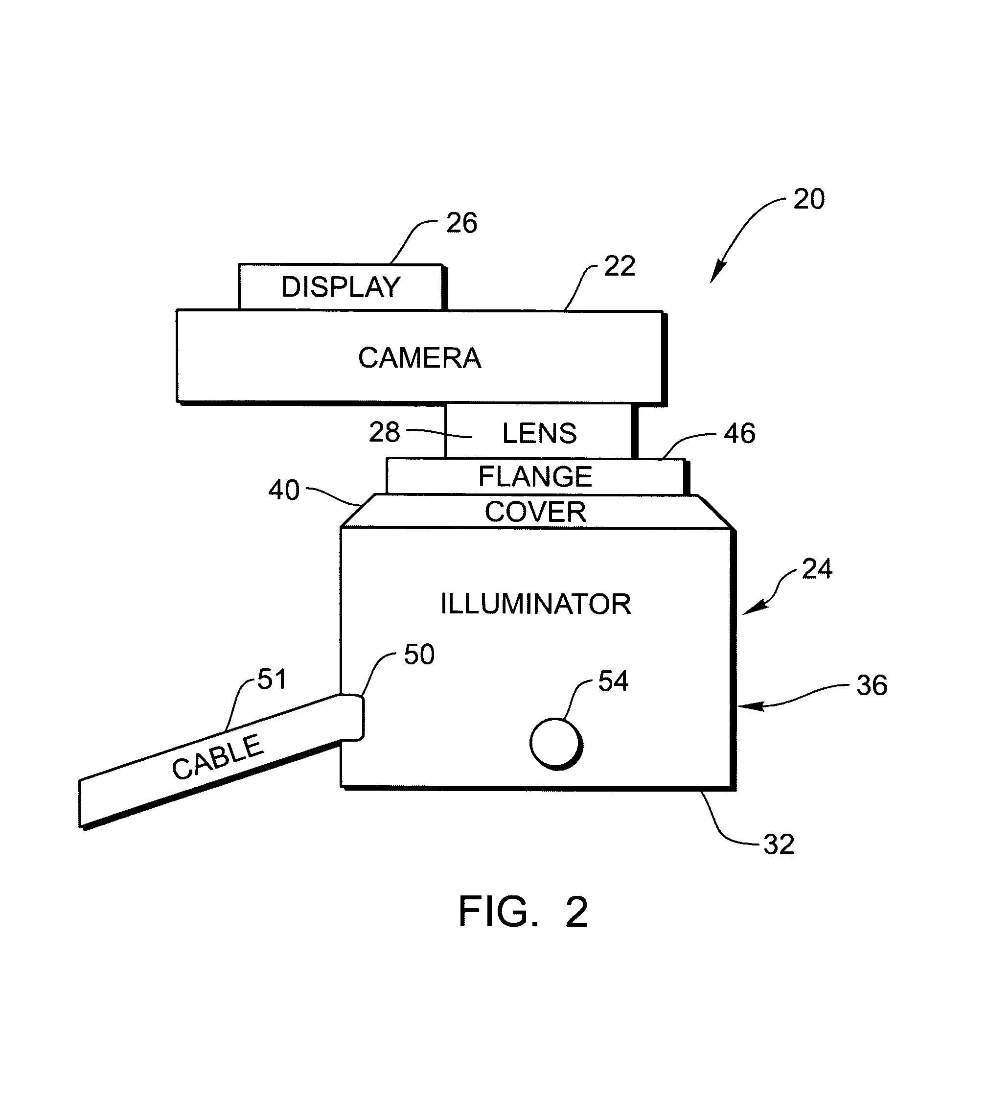
[0022]An imaging device includes a camera, an illuminator to illuminate a target of interest, such as skin, and a display, such as a monitor, for outputting images. In a preferred embodiment, the camera has an image detector 16, such as a charged couple device (CCD). Importantly, the illuminator shades the target of interest from ambient light to prevent background light from entering the target, thereby reducing or eliminating problems associated with ambient light entering the device. Such problems include interference with image acquisition and image processing. Images acquired by the imaging device are pre-processed to reduce background, i.e., brightness variation, reduce noise in the image, and amplify the image. A structure of interest is then detected in the amplified image. In a preferred embodiment, the structure of interest that is detected is a vein. The imaging device and methods described herein can be used to detect structure of interest other than ve...


PUM


Abstract

A method to detect a structure of interest includes shading a target from ambient light. A first plurality of images is acquired from the target. Background in the first plurality of images is reduced to minimize or eliminate brightness variation in the images and to generate a first plurality background-reduced images. A second plurality of images is acquired from the target. Background in the second plurality of images is reduced to generate a second plurality of background-reduced images. Noise in the second plurality of background-reduced images is reduced to generate a noise-reduced image, which is then multiplied to generate an amplified image. A structure of interest is detected in the amplified image. An imaging device that can be used to carry out the method is also included and includes an illuminator that shades the target from ambient light and scatters light.

Description

BACKGROUND OF THE INVENTION[0001]1. Field of the Invention[0002]The invention relates to imaging devices, and more particularly to imaging devices for medical and other uses. The invention is particularly useful for imaging vascular structures in patients to aid in the insertion of a needle during venipuncture.[0003]2. Description of the Related Art[0004]Veins and arteries in many patients are difficult to find. This problem is exacerbated in, for example, dehydrated patients, dark-skin patients, and young patients. Further, unskilled technicians have great difficulty in locating subcutaneous structures even in normal patients. Thus, a device to aid in locating such structures is needed.[0005]Attempts at providing such a device include various devices that illuminate skin to enhance location of veins and arteries. These devices use a variety of light sources, such as laser light, infrared light, flashlights, fiber optics, and ultrasonic waves, for illuminating the skin. For example,...

Claims


Application Information

Patent Timeline
Patent Type & Authority Patents(United States)
IPC IPC(8): G06K9/00A61B5/00A61M5/42G06T5/00G06T5/50G06T7/00
CPCA61B5/0059A61B5/489A61M5/427G06T7/0012G06T2207/30101G06T2207/10048G06T2207/30088
Inventor GEE, JR., JAMES W.PENNYPACKER, CARL
Owner GEE JR JAMES W
Learn More