Elastic track shoe
a technology of elastic body and track shoe, which is applied in the direction of wheel attachment, transportation and packaging, drilling equipment, etc., can solve the problems of deflection and distortion, deflection and distortion, loosening and coming off bolts, etc., and achieves the effect of preventing the peeling of the elastic body, ensuring the friction coefficient with respect to the road surface, and improving the durability of the join
- Summary
- Abstract
- Description
- Claims
- Application Information
AI Technical Summary
Benefits of technology
Problems solved by technology
Method used
Image
Examples
first embodiment
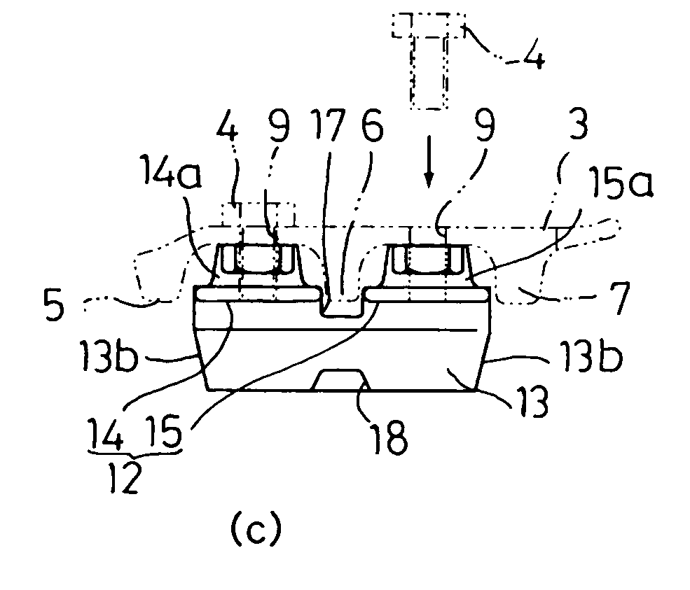
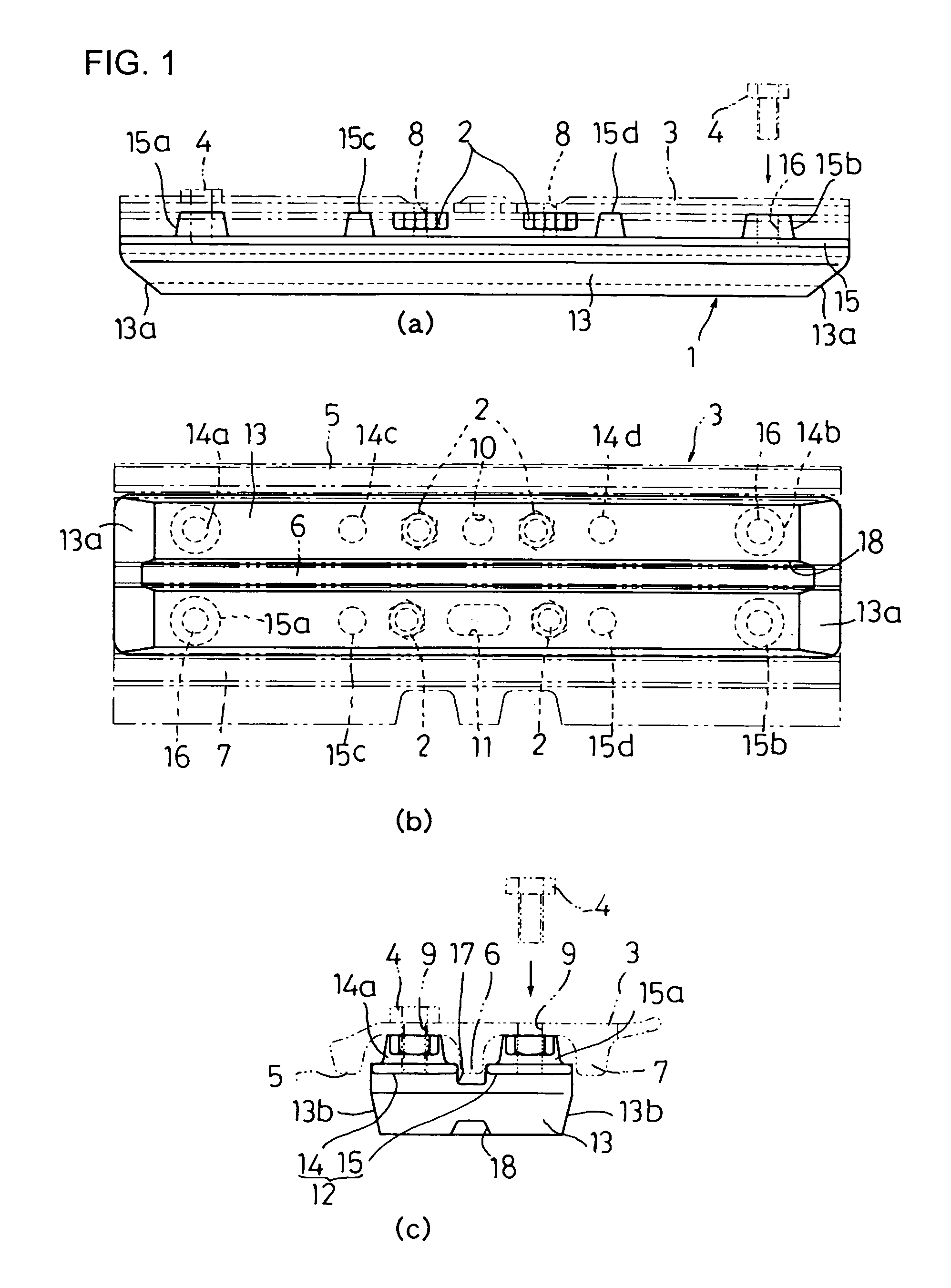
[0037]FIGS. 1(a), 1(b) and 1(c) are a front view, bottom view and side view, respectively, of an elastic track shoe constructed according to the invention.
[0038]An elastic track shoe 1 according to the first embodiment is attached to the ground engaging side of an iron shoe plate 3 by means of a plurality of bolts 4 (four bolts in the first embodiment), the shoe plate 3 being mounted to a crawler track link (not shown) with a plurality of bolts 2 (four bolts in the first embodiment) and nuts (not shown).
[0039]The shoe plate 3 has three grousers 5, 6, 7 in total, which are located at the widthwise center and widthwise ends of the shoe plate 3, extending in a longitudinal direction of its tread. The shoe plate 3 has, at its longitudinal center, bolt insertion holes 8 through which the bolts 2 pass in order to attach the shoe plate 3 to a crawler track link. Provided at positions close to both longitudinal ends are bolt insertion holes 9 through which the bolts 4 pass in order to attac...
second embodiment
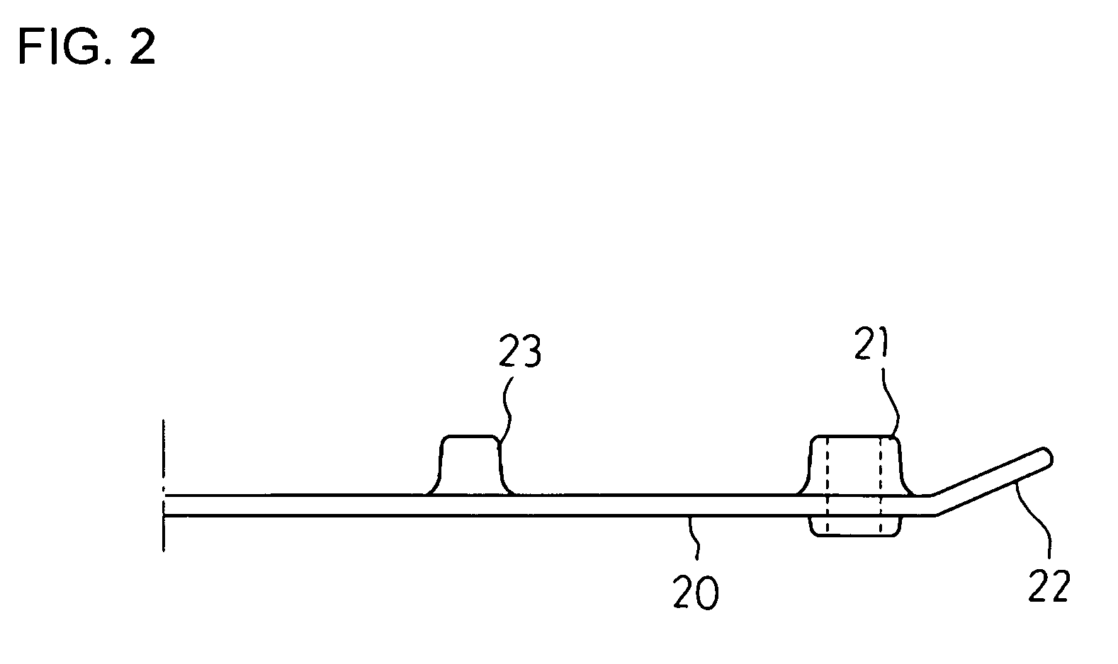
[0044]FIG. 2 is a partial sectional view of a core bar of an elastic track shoe constructed according to the invention.
[0045]The elastic track shoe of the second embodiment is the same as that of the first embodiment except the shape of the core bar. In the second embodiment, a support (boss) 21 is disposed at both longitudinal ends of each core bar portion 20 so as to somewhat project toward the ground engaging side of the core bar portion 20, and the ground engaging side of the area intermediate between the bosses 21 located at both ends is made in the form of a planar surface. The structure of this embodiment is useful particularly for the case where sufficient screw depth is required for the bolts 4 (See FIG. 1) used for attaching the core bar to the shoe plate.
[0046]In the second embodiment, each core bar portion 20 bends to the non ground engaging side at the longitudinal ends thereof, thereby forming inclined faces 22. The provision of the inclined faces 22 offers such an adv...
third embodiment
[0047]FIG. 3(a) is a partial front view of a core bar of an elastic track shoe constructed according to the invention, FIG. 3(b) is a sectional view taken along line A—A of FIG. 3(a), and FIG. 3(c) is a sectional view taken along line B—B of FIG. 3(a).
[0048]The elastic track shoe of the third embodiment is similar to that of the first embodiment except the shape of the cross bar. In the third embodiment, a support 25 is formed at an end of each core bar portion 24 and another support 26 is formed at the middle part of the core bar portion 24. Provided between the supports 25 and 26 and between the support 25 and the leading end of the inclined face 27 are ribs 28. The provision of the ribs 28 allows the load received from the ground surface to be transmitted to the shoe plate without fail and also contributes to a reduction in the weight of the core bar.
PUM
 Abstract
Description
Claims
Application Information
 - R&D
- Intellectual Property
- Life Sciences
- Materials
- Tech Scout
- Unparalleled Data Quality
- Higher Quality Content
- 60% Fewer Hallucinations
Browse by: Latest US Patents, China's latest patents, Technical Efficacy Thesaurus, Application Domain, Technology Topic, Popular Technical Reports.
© 2025 PatSnap. All rights reserved.Legal|Privacy policy|Modern Slavery Act Transparency Statement|Sitemap|About US| Contact US: help@patsnap.com


