
Adjustable spray pattern sprinkler

a sprinkler and pattern technology, applied in the field of irrigating soil, can solve the problems of insufficient spray clearance of sprinklers, inability to adequately or efficiently irrigate with the limited number of spray angles available, and inability to adjust the spray angle, etc., and achieve the effect of relatively low cost and convenient us

Active Publication Date: 2006-12-26
HUSQVARNA AB
View PDF24 Cites 42 Cited by
  • Summary
  • Abstract
  • Description
  • Claims
  • Application Information

AI Technical Summary

Benefits of technology

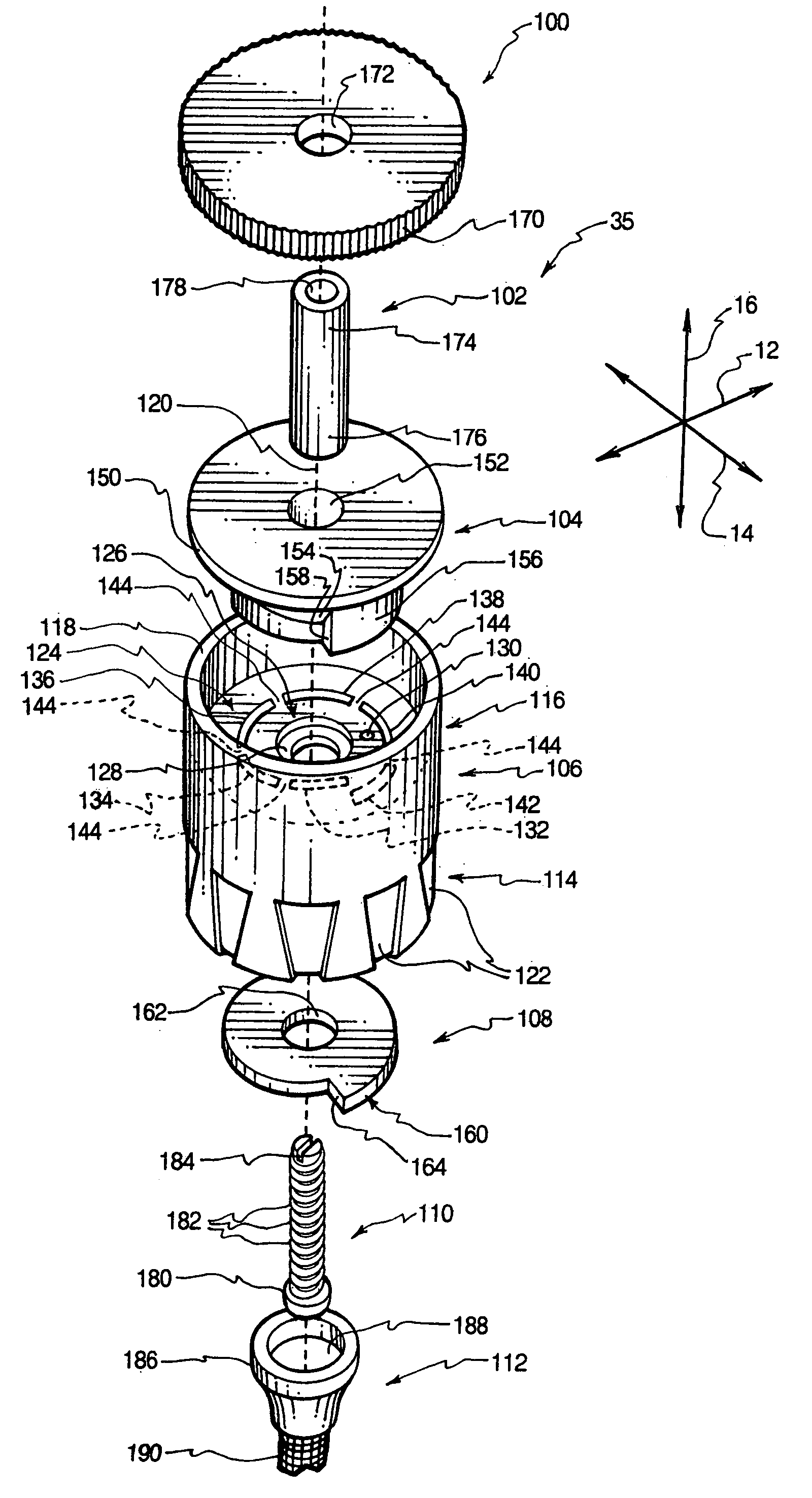
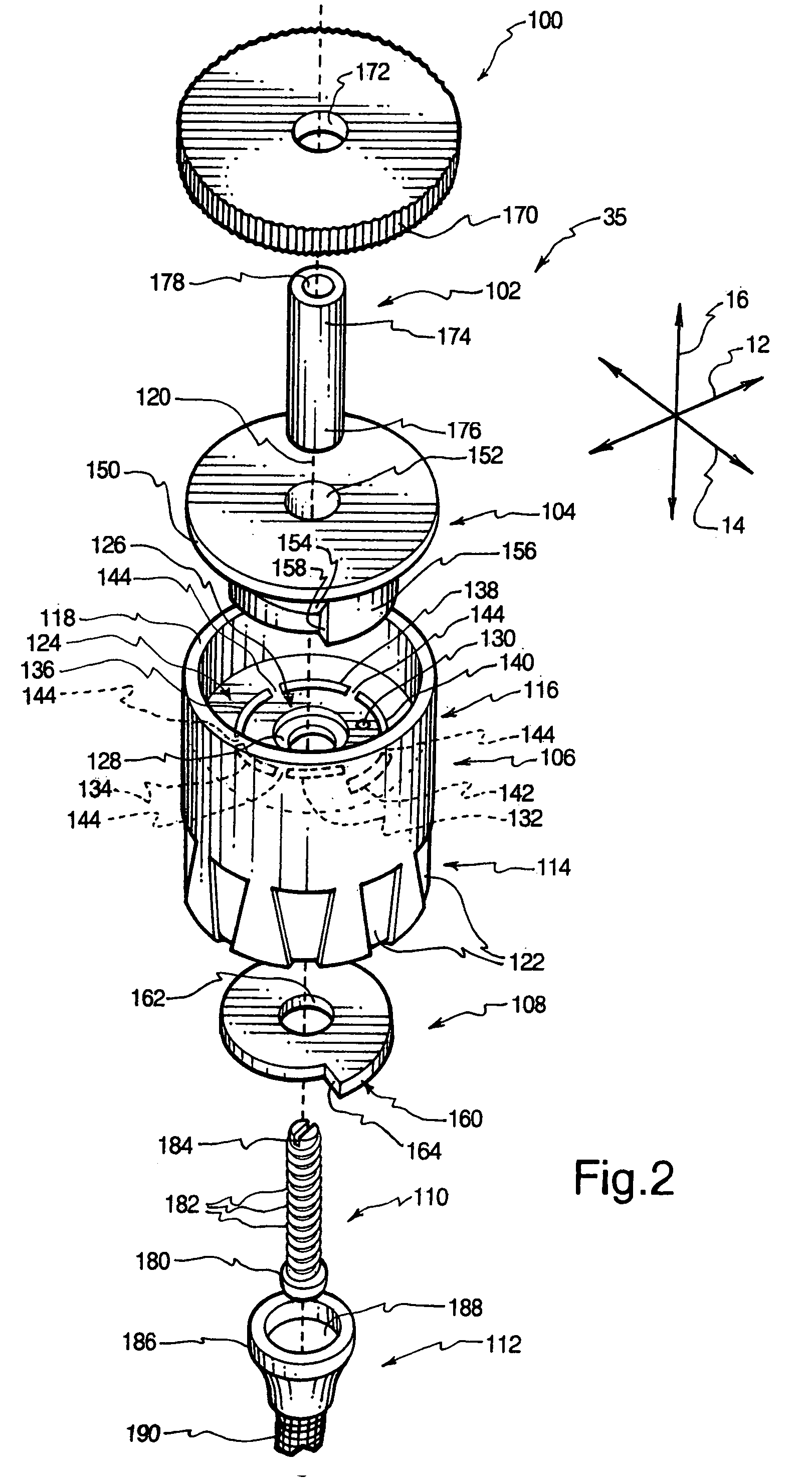
[0017]The spray head may have an adjustment dial, a shaft, a deflector, a housing, a cam, and an adjustment screw. A filter is inserted into the pop-up stem to rest underneath the spray head. The housing has an inlet portion adjacent to the end of the pop-up stem and an outlet portion disposed above (i.e., downstream of) the inlet portion. The housing has an outer wall with a generally tubular shape through which water flows. The housing is centered about a cam axis. Threads are formed on the inside surface of the outer wall to permit threaded engagement of the inlet portion with the pop-up stem. The outer wall has a plurality of indentations disposed on the outer surface of the inlet portion to facilitate rotation of the housing by hand so that the spray head can easily be manually attached to or removed from the pop-up stem.
[0021]The adjustment dial, shaft, deflector, housing, cam, and adjustment screw may be easily manufactured through the use of known methods. According to one example, the housing and the deflector may be made of plastic via injection molding. The shaft may be cut from a stock length of interior threaded, tubular metal or plastic. The adjustment dial and the cam may be stamped from metal or plastic sheets. The adjustment screw may be formed via casting or other known methods.
[0025]The adjustment dial may be rotated to rotate the shaft, thereby rotating the cam. The relative sizes of the cam and the outlet apertures enable the orientation of the cam to determine the angle through which water flows through the outlet apertures. The adjustment dial may be rotated to permit water to flow from the spray head through an arc angle ranging from about 20° to about 360° (full-circle). The adjustment screw may be rotated to move the head of the adjustment screw closer to or further from the tapered bore, thereby controlling the quantity of water distributed by the spray head.
[0027]The vanes are curved in such a manner that water flowing from the outlet apertures impinges against the vanes and causes the deflector to rotate. The water moves through the grooves between the vanes and exits the grooves with tangential, as well as radial, velocity. The rotation of the deflector may provide more even water distribution and attractive operation.
[0029]Like the deflector of the first embodiment, the deflector includes a lip from which a conical portion extends toward the housing. A hub and an orientation post extend from the conical portion toward the housing. The plate of the housing has a central hole and a receiving hole that receive the hub and the orientation post in a manner that prevents relative rotation between the deflector and the housing.
[0033]Through the use of the apparatus and method of the invention, a sprinkler may provide relatively uniform water distribution over a continuously variable angle including a full-circle spray pattern. A sprinkler may alternatively be adjustable between different strip irrigation settings including center strip irrigation, side strip irrigation, and end strip irrigation. Furthermore, such sprinklers may be easy to use and may be produced at relatively low cost. These and other features and advantages of the present invention will become more fully apparent from the following description and appended claims, or may be learned by the practice of the invention as set forth hereinafter.

Problems solved by technology

Some areas, such as those with corners between 90°, 180°, 270°, and 360°, are difficult or impossible to adequately or efficiently irrigate with the limited number of spray angles available.
Unfortunately, known variable arc sprinklers have a number of inherent limitations.
Thus, the sprinkler may not have sufficient spray clearance, or may be damaged by lawn care equipment.
Furthermore, many known variable arc sprinklers are unable to provide an even distribution of water across the selected angle.
Thus, the corresponding soil is unevenly irrigated.
Many known variable arc sprinklers are unable to effectively provide full-circle coverage because the flow of water from the sprinkler head is discontinuous over the adjacent ends of the arc.
Yet further, many known variable arc sprinklers are relatively complex, and are therefore far more expensive than their fixed-angle counterparts.
Some known variable arc sprinklers have parts with relatively complex geometries that cannot be readily produced through the use of economical methods.
Some adjustable sprinklers also have visible parts that are asymmetrical, and therefore may not look attractive to a user.
Still further, known variable arc sprinklers are generally not suitable for strip irrigation because they broadcast water over a pie-shaped or circular area that does not suit the dimensions of typical strips.
Accordingly, the problems described above have not been fully remedied by existing sprinkler designs.

Method used


Image

  • Adjustable spray pattern sprinkler
  • Adjustable spray pattern sprinkler
  • Adjustable spray pattern sprinkler

Examples


Embodiment Construction

[0049]The presently preferred embodiments of the present invention will be best understood by reference to the drawings, wherein like parts are designated by like numerals throughout. It will be readily understood that the components of the present invention, as generally described and illustrated in the figures herein, could be arranged and designed in a wide variety of different configurations. Thus, the following more detailed description of the embodiments of the apparatus, system, and method of the present invention, as represented in FIGS. 1 through 7F, is not intended to limit the scope of the invention, as claimed, but is merely representative of presently preferred embodiments of the invention.

[0050]For this application, the phrases “connected to,”“coupled to,” and “in communication with” refer to any form of interaction between two or more entities, including mechanical, electrical, magnetic, electromagnetic, and thermal interaction. The phrase “attached to” refers to a fo...


PUM


Abstract

A sprinkler has a housing with an inlet portion and an outlet portion in which a first outlet aperture is formed. The first outlet aperture may cooperate with other outlet apertures to define a spiral shape. A cam is disposed upstream of the first outlet aperture. The cam is rotatable about a cam axis to cover varying portions of the outlet apertures. After moving through the outlet apertures, water strikes a deflector and is sprayed outward from the head. The orientation of the cam establishes an arc angle through which water is sprayed, including a full-circle spray pattern. The deflector may be stationary or rotatable. In one alternative configuration, the outlet apertures and each leads to a different strip nozzle. The cam has an open portion that can be rotated into alignment with each of the outlet apertures to determine which of the strip nozzles are active.

Description

BACKGROUND OF THE INVENTION[0001]1. Field of the Invention[0002]The present invention relates to systems and methods for irrigating soil. More specifically, the present invention relates to a sprinkler head and related methods that distribute water over a variable spray pattern.[0003]2. Description of Related Art[0004]Irrigation not only permits foodstuffs to be grown, but also enables the cultivation of attractive plant life that otherwise would not have sufficient water to thrive. Many households now utilize sprinkler systems to provide irrigation in a comparatively uniform and trouble-free manner.[0005]Often, a control unit such as a timer is used to regularly initiate operation of the sprinkler system to automatically provide the desired distribution of irrigation water. The timer is electrically connected to a plurality of electrically operated valves, each of which is able to permit water to flow into a corresponding zone of the sprinkler system. Each zone may have a number of...

Claims


Application Information

Patent Timeline
IPC IPC(8): B05B1/26A01G27/00B05B15/10B05B17/04
CPCB05B1/262B05B1/267B05B1/3026B05B3/0486B05B3/021B05B15/10Y10S239/01B05B15/74
Inventor SCHAPPER, AARONOLSEN, CHRISTIAN M.WILSON, CHADWICK L.
Owner HUSQVARNA AB
Learn More