
Bipolar coagulating instrument

a coagulation instrument and bipolar technology, applied in the field of bipolar electrosurgical instruments, can solve the problems of having to reorient surgical instruments repeatedly, and achieve the effect of convenient electrical communication

Active Publication Date: 2006-12-19
GYRUS MEDICAL LTD
View PDF14 Cites 1315 Cited by
  • Summary
  • Abstract
  • Description
  • Claims
  • Application Information

AI Technical Summary

Benefits of technology

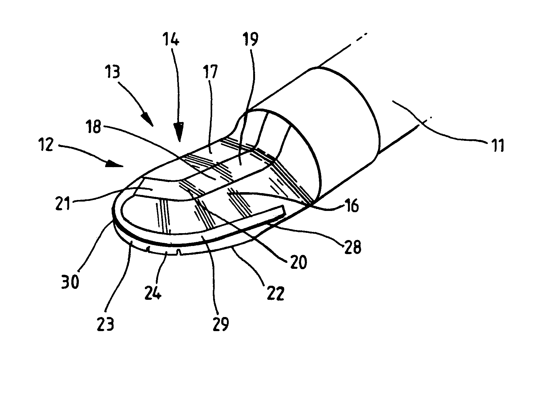
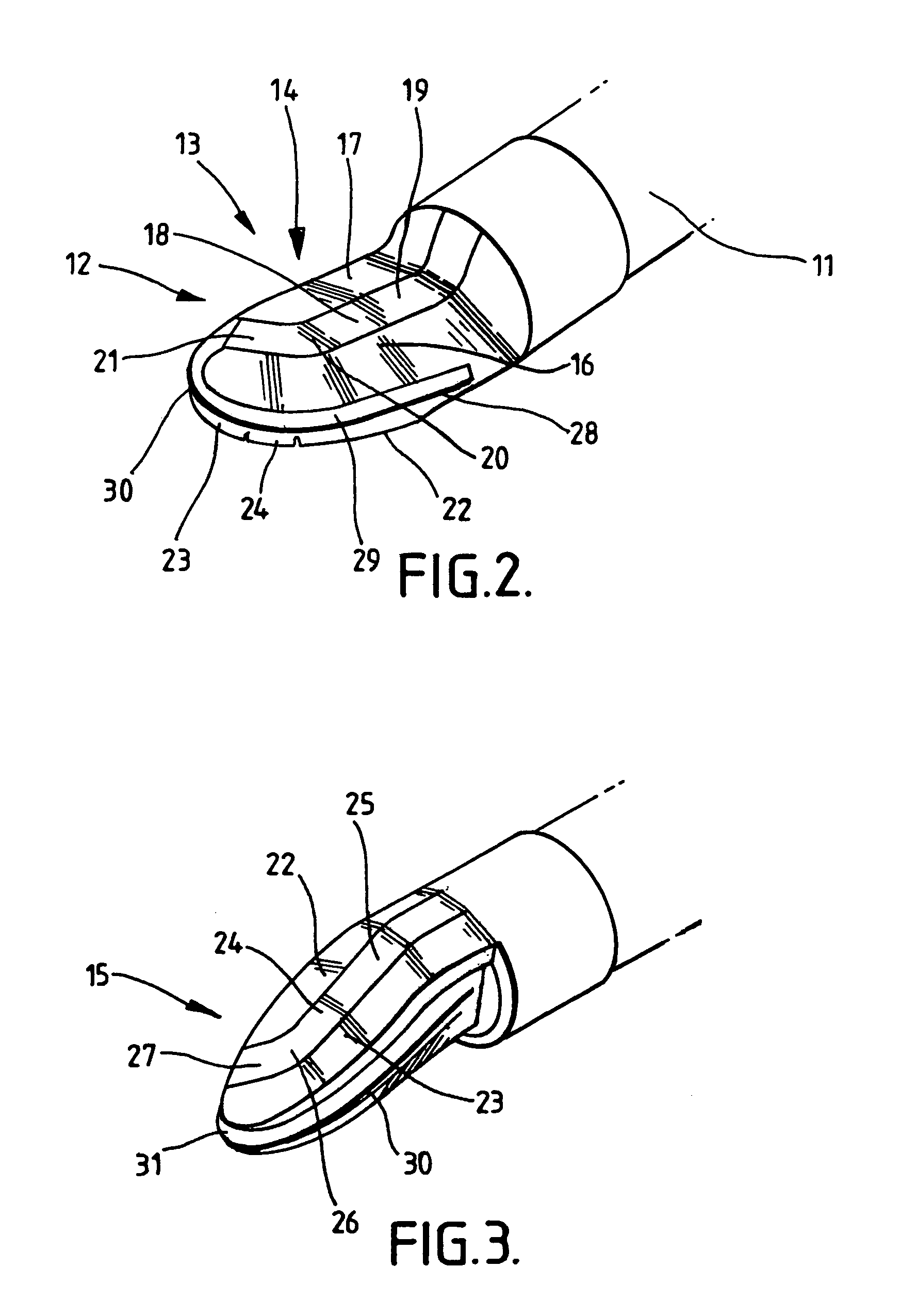
[0011]In a preferred arrangement, there is additionally provided a cutting electrode, the cutting electrode being insulated from each of the first to fourth electrodes. In this way the instrument can be used to both cut and coagulate tissue, typically in a procedure such as a laparoscopic supracervical hysterectomy (LSH). Conveniently, the cutting electrode is located between the upper planar face and the lower planar face. Typically, the intermediate layer of insulating material is two parts, and the cutting electrode is located therebetween. Preferably, the cutting electrode protrudes from an edge of the blade-like electrode assembly. Thus, the edge of the electrode assembly can be used to cut tissue, and coagulation can be performed in any of the regions of the instrument as previously described. In this way, both cutting and coagulation can be performed with only minimal movement and re-orientation of the instrument being necessary, as is required in a minimally-invasive procedure.

Problems solved by technology

By definition, the procedure is taking place in a confined space, and it is often difficult or inconvenient to have to re-orient the surgical instrument repeatedly in order to achieve such coagulation.

Method used


Image

  • Bipolar coagulating instrument
  • Bipolar coagulating instrument
  • Bipolar coagulating instrument

Examples


Embodiment Construction

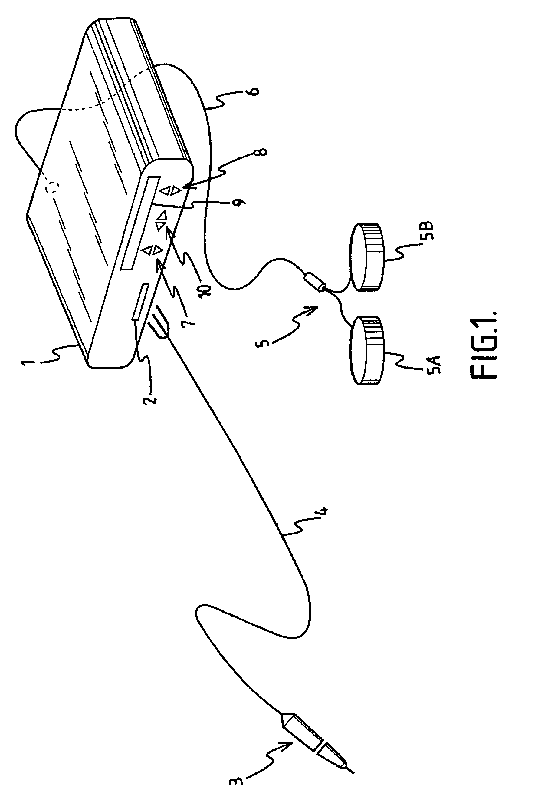
[0016]Referring to FIG. 1, a generator 1 has an output socket 2 providing a radio frequency (RF) output for an instrument 3 via a connection cord 4. Activation of the generator 1 may be performed from the instrument 3 via a connection in the cord 4, or by means of a footswitch unit 5, as shown, connected to the rear of the generator by a footswitch connection cord 6. In the illustrated embodiment, the footswitch unit 5 has two footswitches 5A and 5B for selecting a coagulation mode and a cutting mode of the generator 1 respectively. The generator front panel has push buttons 7 and 8 for respectively setting coagulation and cutting power levels, which are indicated in a display 9. Push buttons 10 are provided as an alternative means for selection between coagulation and cutting modes.

[0017]Referring to FIGS. 2 and 3, the instrument 3 is shown having a longitudinally-extending shaft 11 and a blade-like electrode assembly 12. The electrode assembly 12 is in the form of a spatula 13, in...


PUM


Abstract

A bipolar coagulating instrument includes a blade-like electrode assembly comprising an upper planar face and a lower planar face separated by an intermediate portion of insulating material therebetween. The upper face includes first and second electrodes separated by a first insulating member, and the lower face includes third and fourth electrodes separated by a second insulating member. The first and second insulating members are out of correlation one with respect to the other, such that there is at least one region in which the first electrode overlies the third electrode, and at least one other region in which the first electrode overlies the fourth electrode. A cutting electrode is provided between the upper and lower faces, extending marginally beyond the periphery thereof.

Description

BACKGROUND OF THE INVENTION[0001]This invention relates to a bipolar electrosurgical instrument such as a scalpel blade. Such instruments are commonly used for the coagulation and / or cutting of tissue in surgical intervention, most commonly in “keyhole” or minimally-invasive surgery, but also in “open” surgery.[0002]Electrosurgical devices generally fall into two categories, monopolar and bipolar. In a monopolar device, a radio frequency signal is supplied to an active electrode which is used to treat tissue at a target site, an electrical circuit being completed by a grounding pad which is generally a large area pad attached to the patient at a location remote from the target site. In contrast, in a bipolar arrangement, both an active and a return electrode are present on the instrument, and the current flows from the active electrode to the return electrode. The present invention relates to a bipolar device.[0003]In minimally-invasive surgery, it is essential to be able to coagula...

Claims


Application Information

Patent Timeline
Patent Type & Authority Patents(United States)
IPC IPC(8): A61B18/18A61B18/14
CPCA61B18/1402A61B2018/00607A61B2018/126A61B2018/1412
Inventor EBBUTT, JULIAN MARKATWELL, ANTHONY KEITH
Owner GYRUS MEDICAL LTD
Learn More