Blood rheology measuring apparatus
a technology of blood rheology and measuring apparatus, which is applied in the field of blood rheology measuring apparatus, can solve the problems of low blood rheology, difficult continuous test, and blood rheology being measured only at medical institutions
- Summary
- Abstract
- Description
- Claims
- Application Information
AI Technical Summary
Benefits of technology
Problems solved by technology
Method used
Image
Examples
embodiment 1
[0076](Embodiment 1)
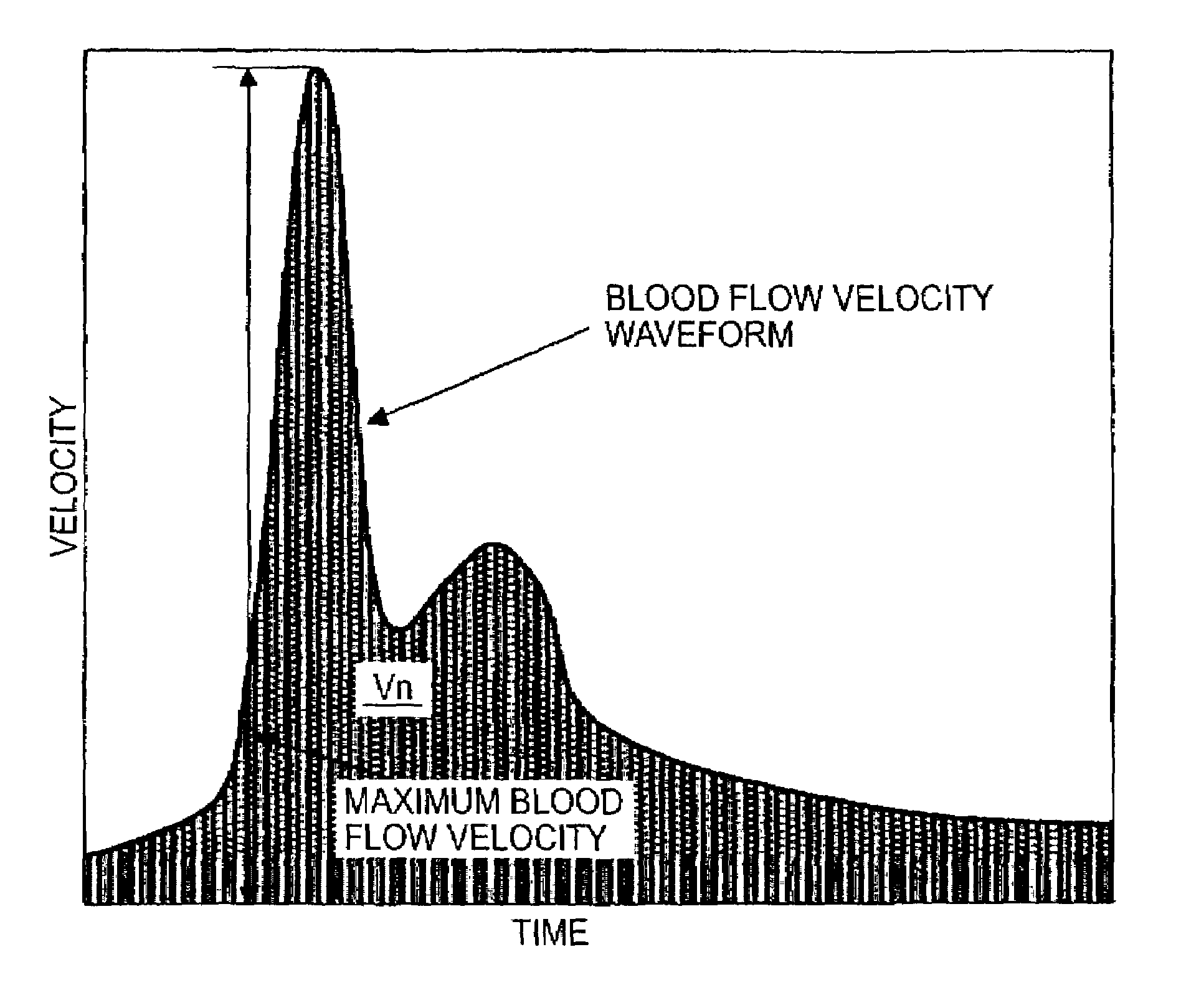
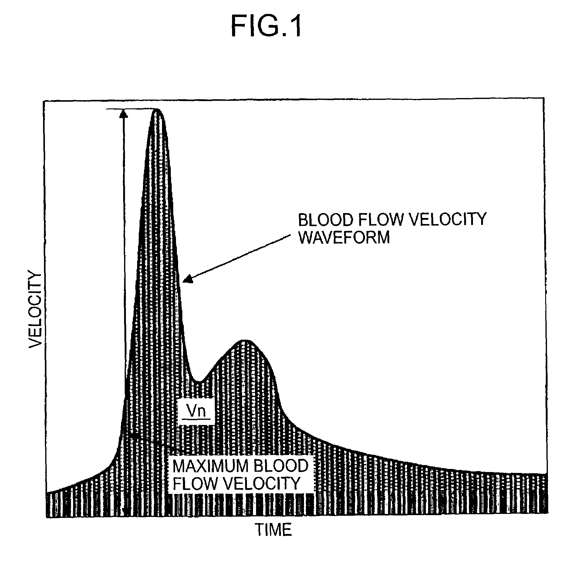
[0077]An explanation will be given of a blood rheology measuring apparatus according to an embodiment of the invention in reference to the attached drawings. The apparatus is constituted by the first blood rheology analyzing method according to the invention of calculating the ratio by dividing the maximum blood flow velocity Vx shown in FIG. 1 by an integrated value of a pulse velocity waveform (an integrated value of a pulse velocity waveform in one period of pulse). FIGS. 6A and 6B are views showing an outlook constitution of the embodiment of the blood rheology measuring apparatus used in the embodiment. As shown by FIG. 6A, the blood rheology measuring apparatus is constituted by being classified in two of a finger ring portion 1 and a signal processing portion 2. FIG. 6B illustrates a section taken along a line A–A′ of FIG. 6A with regard to Embodiment 1. As shown by FIG. 6B, an ultrasonic wave sensor portion 3 is present on an inner side of the finger ring...
embodiment 2
[0085](Embodiment 2)
[0086]According to Embodiment 2 of the invention, there is provided body temperature compensating means to above Embodiment 1. A mode of putting the blood rheology measuring apparatus on the finger is similar to that of FIG. 6. Further, FIG. 9 shows a perspective sectional view of the finger ring portion 1 viewing from the B direction of FIG. 6B. The blood rheology measuring apparatus of Embodiment 2 is constituted by being classified in two of the finger ring portion 1 and the signal processing portion 2 similar to Embodiment 1 and as shown by FIG. 9, there are present the ultrasonic wave sensor portion 3 and a temperature sensor 7 on the inner side of the finger ring portion 1. Further, also the temperature sensor 7 is attached to the portion of the finger 6 shifted to the left of the center of the belly in order to measure temperature at a vicinity of the artery 5 similar to the ultrasonic sensor portion. Thereby, reflection from the artery can firmly be caugh...
embodiment 3
[0092](Embodiment 3)
[0093]FIG. 11 is a view showing an outlook constitution of a blood rheology measuring apparatus according to a third embodiment of the invention. Although the embodiment is similar to above Embodiment 1 in that the embodiment is constituted by the first blood rheology analyzing method according to the invention of calculating blood rheology by dividing the maximum blood flow velocity Vx shown in FIG. 1 by the integrated value of the pulse velocity waveform (the integrated value of the pulse velocity waveform in one period of pulse), the embodiment differs from Embodiment 1 in that a position of measuring blood flow is basically disposed at a finger tip portion frontward from the first joint of the finger. As shown by FIG. 11, the blood rheology measuring apparatus is constructed by a constitution including the signal processing portion 2 in a mouse type blood rheology measuring apparatus 11.
[0094]FIG. 12 illustrates a section taken along a line A–A′ of FIG. 11. A...
PUM
 Abstract
Description
Claims
Application Information
 - R&D Engineer
- R&D Manager
- IP Professional
- Industry Leading Data Capabilities
- Powerful AI technology
- Patent DNA Extraction
Browse by: Latest US Patents, China's latest patents, Technical Efficacy Thesaurus, Application Domain, Technology Topic, Popular Technical Reports.
© 2024 PatSnap. All rights reserved.Legal|Privacy policy|Modern Slavery Act Transparency Statement|Sitemap|About US| Contact US: help@patsnap.com


