
Device for cleaning interdental spaces

Inactive Publication Date: 2006-12-12
LESAGE
View PDF6 Cites 6 Cited by
  • Summary
  • Abstract
  • Description
  • Claims
  • Application Information

AI Technical Summary

Benefits of technology

[0010]An object of the present invention is to provide a device for cleaning interdental spaces that is more efficient and easier to use than the current state of the art represented principally by interdental brushes.
[0017]It will be understood that when the interdental cleaning device is put into position the brush is entirely inside the tubular element. It therefore cannot be mechanically damaged. Moreover, this initial positioning is facilitated because the assembly consisting of the tubular element and the gripping means has sufficient mechanical strength to allow the soft tissue, such as the lip, cheek or tongue, to be moved away while bearing in the interdental space. Furthermore, the profiled open end of the tubular element considerably facilitates the initial positioning of the cleaning device at the entrance to the interdental zone.

Problems solved by technology

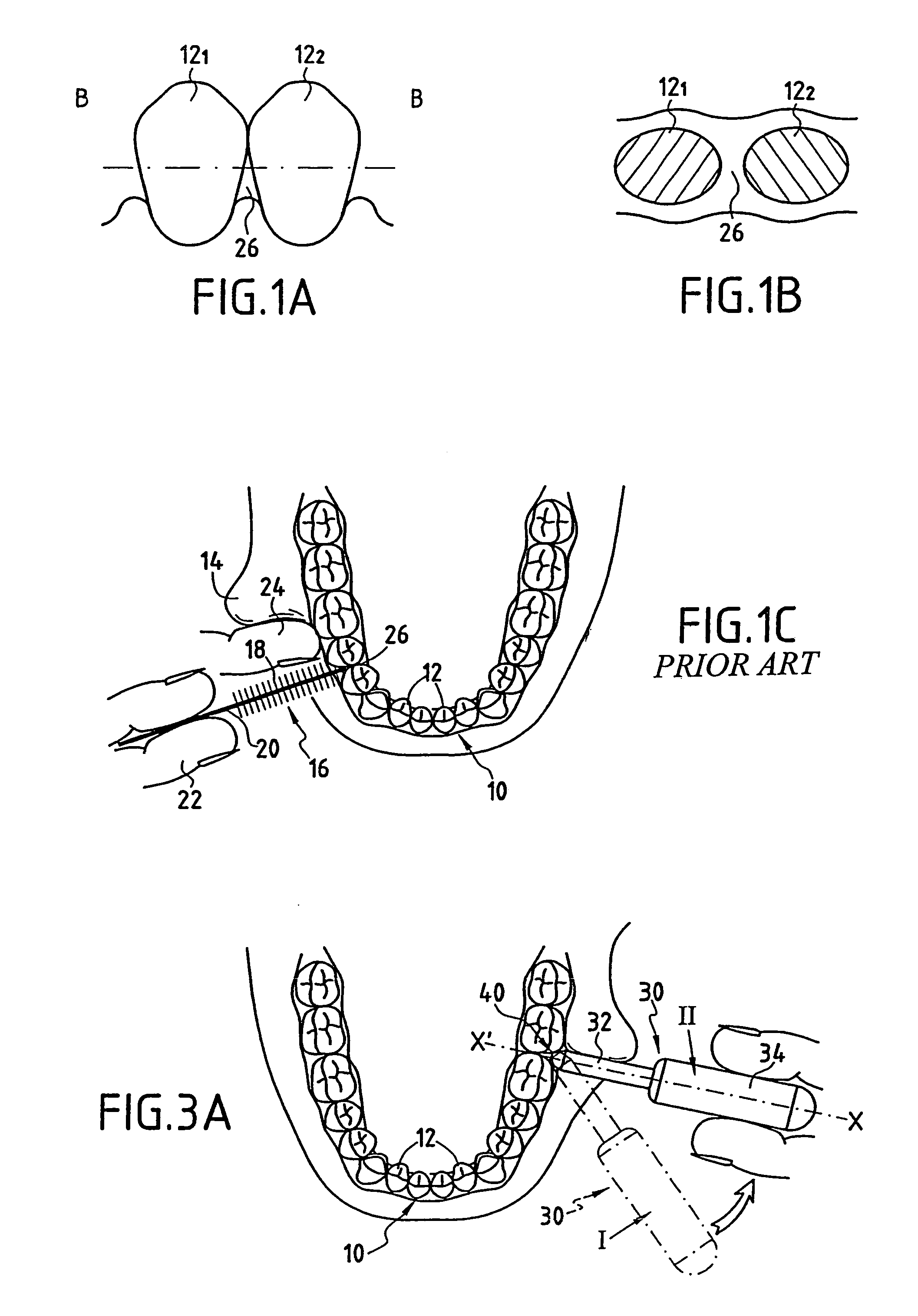
However, these brushes have a number of drawbacks that either affect the cleaning efficiency or dissuade the user from continuing to use them.
Moreover, the lips and cheeks cannot be pushed back easily in order to allow comfortable positioning of the brush.
Lastly, patients do not always have the skill required to present the end of the brush conveniently opposite the interdental space to be cleaned.
All the above considerations mean that the use of brushes of known type is therefore awkward, and the deformation of the brush gives rise to poor cleaning or early destruction of the equipment, and also to the frequent cessation of use of the cleaning device on the part of the user.

Method used


Image

  • Device for cleaning interdental spaces
  • Device for cleaning interdental spaces
  • Device for cleaning interdental spaces

Examples


first embodiment

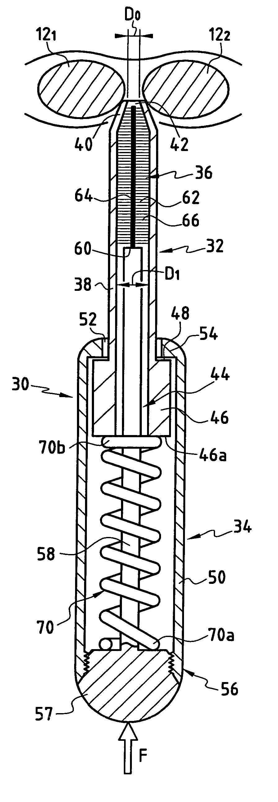
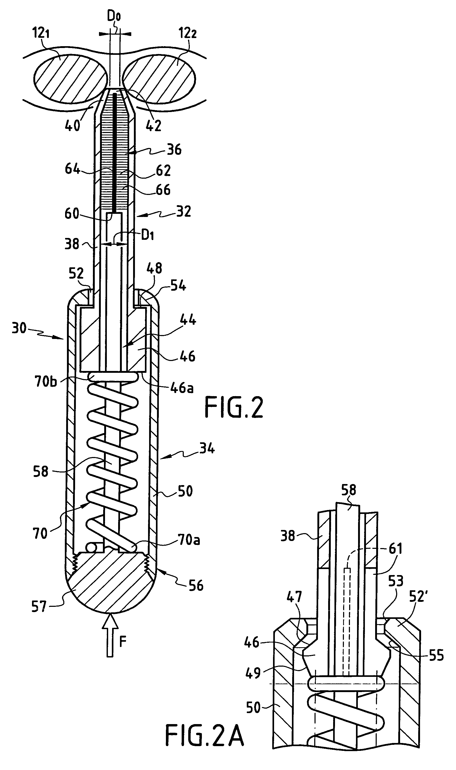
[0029]With reference, firstly, to FIG. 2, a description will be given of an interdental cleaning device 30. This device consists essentially of a tubular guide element 32, gripping means 34, cleaning means 36 forming a brush, and support means 58.

[0030]More precisely, the tubular guide element 32 includes a tubular piece 38 of which a first end 40 ends in a frustoconical shape for location and positioning in the interdental space 44. In its common part, the tubular piece 38 has an internal diameter D0, whereas its open end 42 has a diameter D1 less than D0. The second end 44 of the tubular piece 38 constitutes a widened part 46 that defines a shoulder 48 on its front face.

[0031]The gripping means 34 consist of a tubular body 50 with a first end 52 that is open to receive the tubular piece 38. The open end 52 includes an edge 54 that is able to cooperate with the shoulder 48 of the tubular piece. The second end 56 of the tubular body 50 is closed by a base 57. Mounted on this base 57...

second embodiment

[0041]With reference, now, to FIG. 4, a description will be given of the device for cleaning interdental spaces, which bears the reference 80. The device consists of a tubular element 82 with a first open end 84 that has a frustoconical shape and a second end 86 that is open and has a recess 88 close to this second end 86. Mounted slidably in the tubular piece 82 is a cylindrical piece 90 forming the support means, the first end 92 of which serves as a pusher for the brush 62. More precisely, the spindle 64 of the brush is fixed on the end 92 of the cylindrical piece 90. The second end 94 of the cylindrical piece 90 is extended by gripping means or handles 96 that emerge from the tubular piece 82 via the recess 88. The handle 96 is provided with an elastic leaf spring 98, a first end 98a of which is secured to the handle 96 and the second end 98b of which bears on the edge 86a of the end 86 of the tubular piece 82.

[0042]Through the effect of the leaf spring 98, the cylindrical piece...


PUM


Abstract

A device for cleaning interdental spaces has a tubular guide element having a first profiled open end to allow its positioning at the entry to an interdental space. A cleaning member mounted movably in the tubular guide element, fixed to a first end of a support member, the support member having a fixed longitudinal direction relative to the axis of the tubular guide element. A gripping member is provided for moving the cleaning member between a first position, in which they are entirely arranged inside the tubular element, and a second position, in which they are arranged entirely outside the first end of the tubular element.

Description

BACKGROUND OF THE INVENTIONThe subject of the invention is a device for cleaning interdental spaces.[0001]The most well-known device for cleaning interdental spaces is generally called a brush. These cleaning means consist of a twisted metal core approximately 1 mm in diameter on which bristles defining a cylindrical or conical volume 5 to 10 mm in diameter are fixed.[0002]They are often provided with a reasonably sophisticated handle to enhance their ergonomics. Because of its small size, this brush can effectively be inserted in the space between two adjacent teeth and efficiently clean that area.[0003]However, these brushes have a number of drawbacks that either affect the cleaning efficiency or dissuade the user from continuing to use them.[0004]These drawbacks will be explained with reference to the appended FIGS. 1A, 1B and 1C.[0005]In FIG. 1C, a lower jaw 10 with teeth 12 and the lateral buccal wall 14 have been shown. This figure also shows a brush 16 with its bristles 18 an...

Claims


Application Information

Patent Timeline
IPC IPC(8): A61C3/00A46B7/02A61C15/00
CPCA46B7/023A61C15/00A46B2200/108
Inventor LESAGE
Owner LESAGE
Learn More