
Laser spectroscopy/chromatography drill bit and methods

a chromatography and laser spectroscopy technology, applied in the field of wellboring equipment, can solve the problems of high cost, extensive wear and/or damage of drill bits used to drill through hard formations, and requires a substantial amount of time, so as to reduce the amount of wear and damage.

Active Publication Date: 2006-12-12
GAS TECH INST
View PDF14 Cites 89 Cited by
  • Summary
  • Abstract
  • Description
  • Claims
  • Application Information

AI Technical Summary

Benefits of technology

This patent describes a drilling apparatus that can drill through difficult geological formations without causing damage to conventional drill bits. The apparatus includes a laser cutting assembly and a vacuum assembly that captures vapors generated by the laser cutting assembly. The vapors can be analyzed using chromatographic analysis or spectroscopic analysis, and the drill bit assembly can also include a mechanical cutting element for removing rock. The laser cutting assembly can be used independently to remove rock or reinforce wellbore walls with unstable formations. Overall, this drilling apparatus can improve drilling efficiency and safety.

Problems solved by technology

However, frequently these reserves are disposed beneath hard geological formations, e.g. rocks, which may even be impenetrable using conventional drilling equipment.
Drilling of such hard formations requires a substantial amount of time and generally results in high costs.
In addition, the drill bits used to drill through these hard formations are subject to extensive wear and / or damage.
Impenetrable formations require the use of overly complex drilling routes in order to circumvent the formations and, in some cases, may result in complete abandonment of the drilling operation.
In addition to hard geological formations, unstable formations, e.g. shale, are frequently encountered, which formations may cause damage to and / or loss of drilling equipment.
Unstable formations may also cause entrapment and subsequent abandonment of the drilling equipment.
However, when lasers are used to perform drilling, the materials being drilled are vaporized, as a result of which there remain no shards of rock for analysis.

Method used


Image

  • Laser spectroscopy/chromatography drill bit and methods
  • Laser spectroscopy/chromatography drill bit and methods
  • Laser spectroscopy/chromatography drill bit and methods

Examples


Embodiment Construction

[0020]As used herein, the term “downstream” refers to a direction towards the front of the drill bit assembly. As used herein, the term “upstream” refers to a direction towards the back of the drill bit assembly.

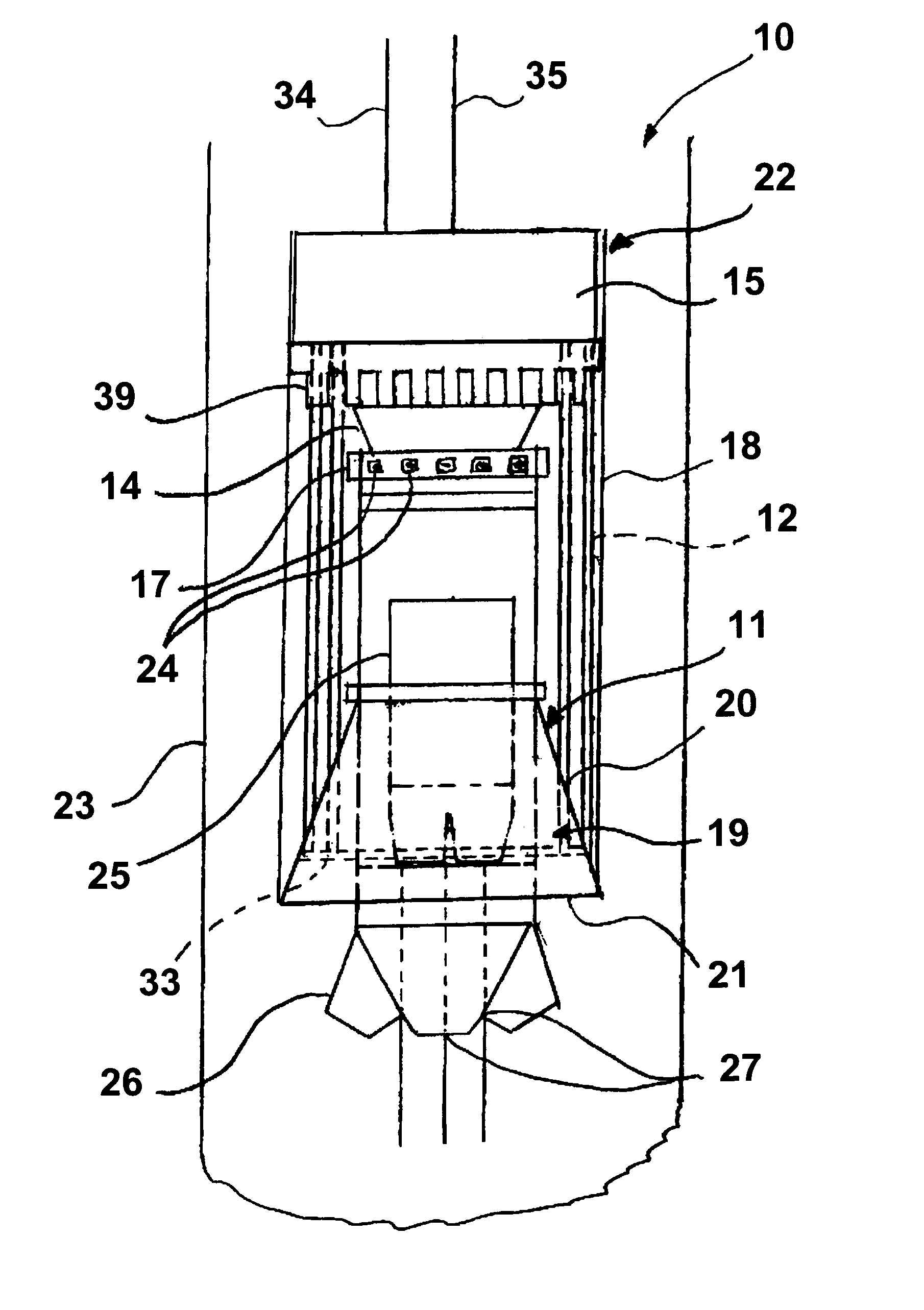
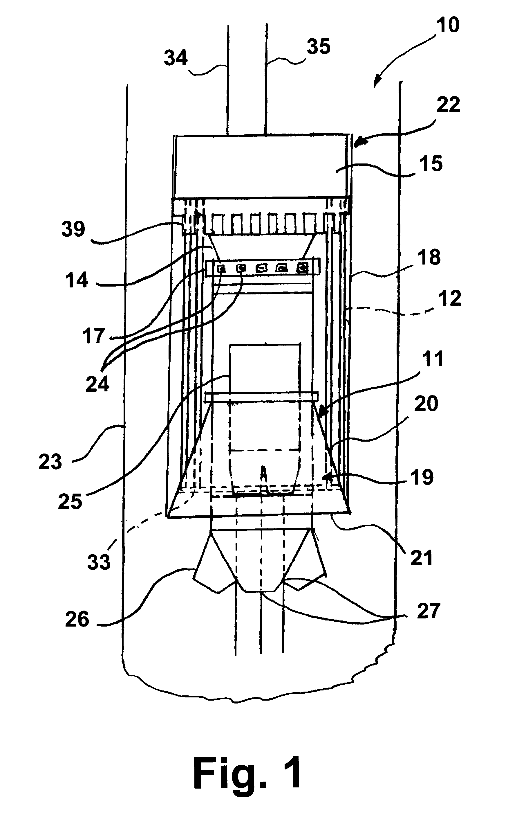
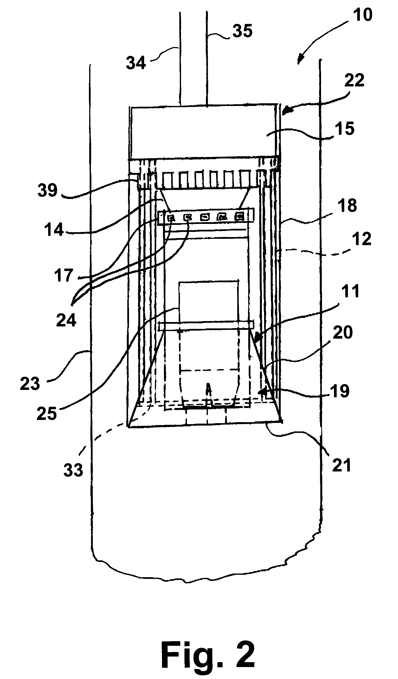
[0021]The invention disclosed herein is a drilling apparatus comprising a drill bit assembly that includes a laser drilling system, which may be of any design suitable for drilling through rock formations, coupled with one or more additional features. In accordance with one preferred embodiment of this invention, the drill bit assembly comprises at least one conventional mechanical cutting element, whereby the drill bit assembly is able to provide both a cutting function and a separate heating function. The cutting function is provided by the conventional cutting elements while the heating function is provided by the laser drilling system which comprises a laser source that projects at least one laser beam ahead of the conventional cutting elements during the well-boring pro...


PUM

PropertyMeasurementUnit
laser spectroscopyaaaaaaaaaa
areaaaaaaaaaaa
transmissionaaaaaaaaaa

Abstract

A drilling apparatus for well-boring having a drill bit assembly which includes a laser cutting assembly and a vacuum assembly. The vacuum assembly is adapted to intake vapors generated by the laser cutting assembly proximate the drill bit assembly during operation of the drilling apparatus. The collected vapors may then be processed by a chromatographic analyzer to determine the characteristics of the rock formation being drilled.

Description

BACKGROUND OF THE INVENTION[0001]1. Field of the Invention[0002]This invention relates to a well-boring apparatus for drilling of subterranean formations for the recovery of fossil fuel deposits in the form of gas, oil and other liquified products. More particularly, this invention relates to an apparatus for drilling oil and gas wells comprising a hybrid drill bit, which provides both a cutting function and a separate heating function. The cutting function is provided by conventional cutting elements while the heating function is provided by a laser source that projects at least one laser beam ahead of the drill bit during the well-boring process to soften and / or melt materials, such as rock formations, disposed in the drilling path. This invention also relates to a well-boring apparatus comprising a drill bit assembly comprising at least one of a chromatographic analysis system and a laser spectroscopy assembly, whereby analysis of materials (e.g. rocks and vapors) disposed in the...

Claims


Application Information

Patent Timeline
Patent Type & Authority Patents(United States)
IPC IPC(8): E21B7/15E21B10/36E21B47/00E21B49/08E21C25/00G01N21/15G01N21/31
CPCE21B7/15E21B49/081B23K26/03B23K26/032B23K26/1405B23K26/381B23K26/4075G01N21/31G01N2021/151G01N2030/0095B23K26/142B23K26/382B23K26/40B23K2103/50E21B47/013
Inventor BATARSEH, SAMIHPERRY, KENTGAHAN, BRIAN C.
Owner GAS TECH INST
Learn More