
Air distribution arrangement for rack-mounted equipment

a rack-mounted computer and data storage technology, which is applied in the direction of electrical apparatus, electrical apparatus casings/cabinets/drawers, cooling/ventilation/heating modifications, etc., can solve the problems of computer and data storage equipment in the upper portion of the cabinet being more susceptible to damage, computer and data storage equipment in the lower portion of the cabinet being prone to failure, etc., to achieve the effect of minimizing the loss of pressurized air

Inactive Publication Date: 2006-12-05
TUREK JAMES R +2
View PDF6 Cites 137 Cited by
  • Summary
  • Abstract
  • Description
  • Claims
  • Application Information

AI Technical Summary

Benefits of technology

"The present invention provides an improved air distribution arrangement for a cabinet that contains rack-mounted equipment that generates heat in use. The arrangement includes a plenum structure with adjustable side and top walls and a gasket seal to minimize air loss. The air box contains one or more fans to draw ambient air from adjacent the floor and move it to the plenum at a rate of at least 850 cfm. The plenum can be adjusted to accommodate a variety of industry cabinets. The air distribution arrangement can be part of a cabinet or an add-on feature. The air distribution arrangement cools the rack-mounted equipment by supplying air to the faces of the equipment. Excess pressure in the plenum can be relieved by pressure relief means in at least one wall defining the plenum."

Problems solved by technology

Heat build-up within the cabinet from the computer and data storage equipment is a long standing problem, for the heat can cause failure of the computer and data storage equipment housed within the cabinet.
Computers and data storage equipment in the upper portion of the cabinets are more susceptible to damage, since heat rises, however, when a large amount of heat is present within the cabinet, computer and data storage in the lower portion of the cabinet can fail as well.

Method used


Image

  • Air distribution arrangement for rack-mounted equipment
  • Air distribution arrangement for rack-mounted equipment
  • Air distribution arrangement for rack-mounted equipment

Examples


Embodiment Construction

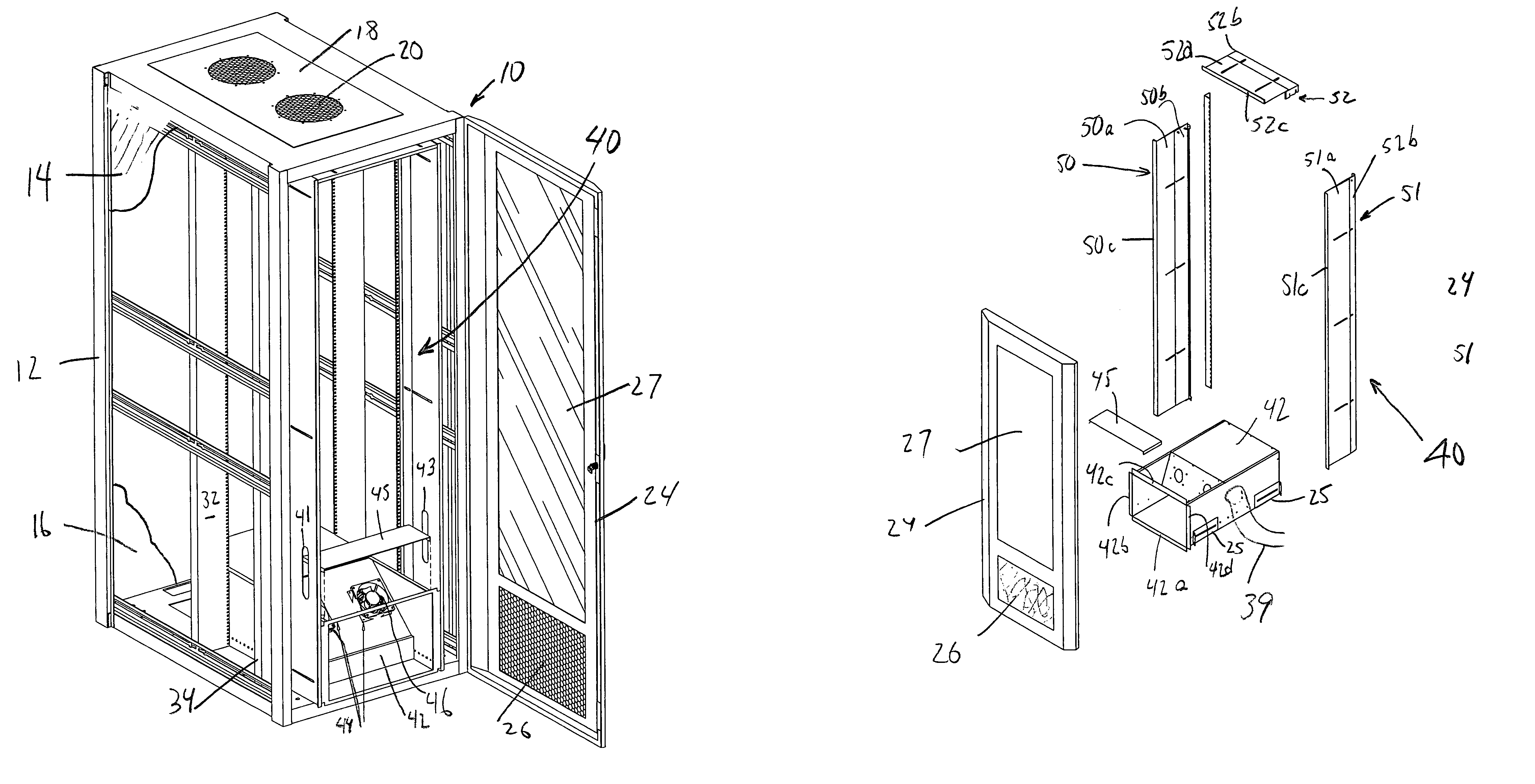
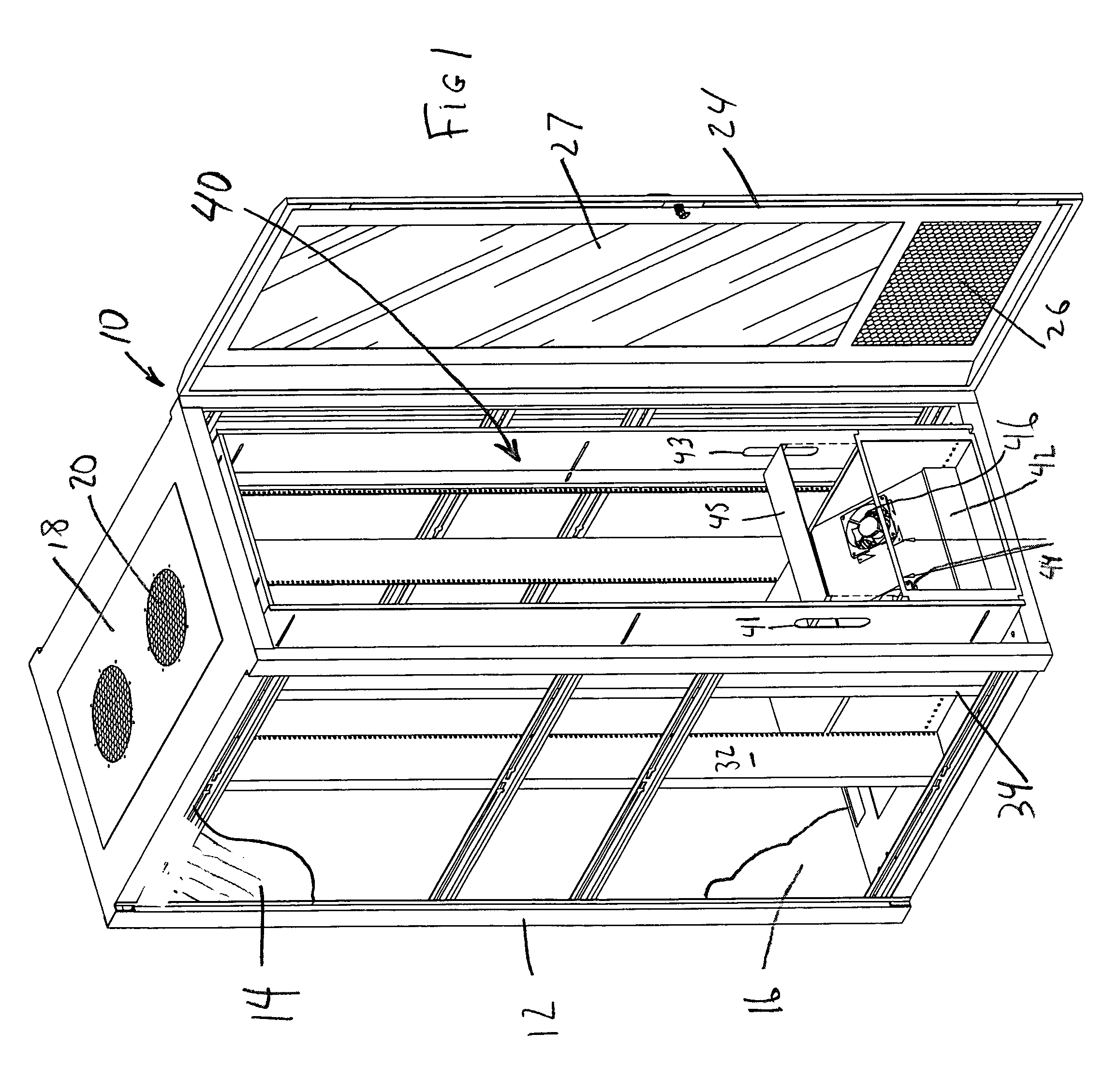
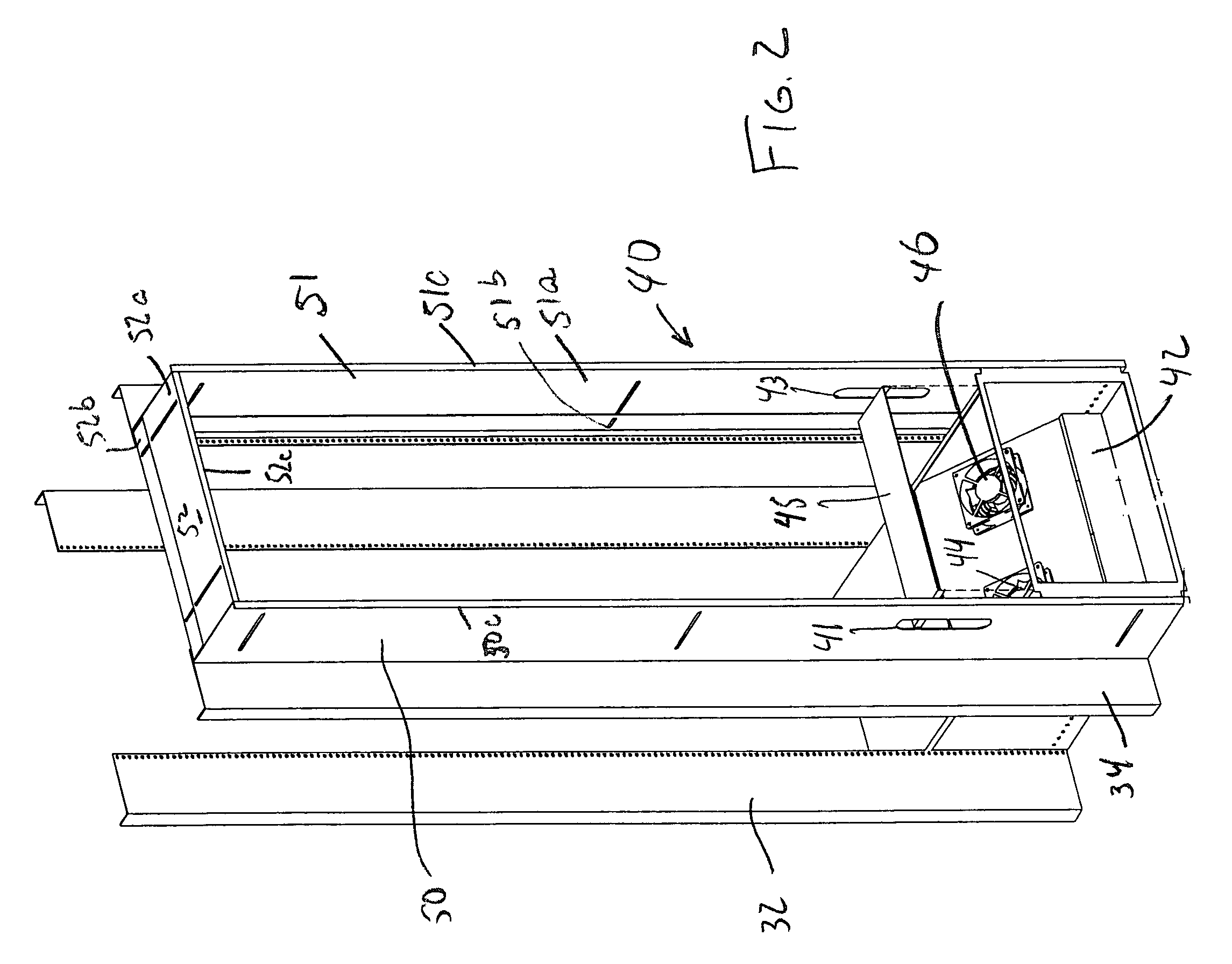
[0027]There is shown in the drawing a cabinet for containing rack-mounting equipment that generates heat and the air distribution arrangement of the present invention which supplies cooling air to the rack-mounted equipment in an inexpensive and effective manner. The cabinet 10 may comprise framework 12 for supporting side walls 14, a rear door 16, and a top wall 18 with vent opening 20. A door 24 is constructed and arranged to be secured to the framework 12 for closing the front of the cabinet. The door 24 includes a mesh grille 26 to permit air to enter the cabinet 10 from the lower front thereof. The upper portion 27 of the door 24 is preferably a solid anti-static acrylic.

[0028]Disposed within the cabinet 10 is a rack 30 comprising spaced apart vertical supports 32, 34 supporting rails 36 upon which the rack-mounted equipment 37 may be supported. As seen in FIG. 1, the rack 30 is spaced at the sides from the cabinet 10 approximately the width of the vertical supports 32, 34.

[002...


PUM


Abstract

An air distribution arrangement is adapted to be arranged in a cabinet for housing rack-mounted equipment that generates heat in use. The arrangement can be part of the cabinet when constructed or it can be an add-on feature. The arrangement includes plenum structure comprising side walls and a top wall that cooperates with the front door of the cabinet and the faces of the rack-mounted equipment to define a plenum. An air box in the cabinet draws ambient air from adjacent the floor into the plenum at a rate of at least 850 cfm. The ambient air is cooler than the air in the cabinet. The faces of the rack-mounted equipment have openings for receiving the ambient air to cool the interiors thereof. After cooling the rack-mounted equipment the air can be exhausted back to the ambient. The side walls and the top wall of the arrangement are adjustable to permit adjustment of the depth of the plenum. Pressure in the plenum can be relieved by slots in the plenum structure.

Description

TECHNICAL FIELD[0001]This invention pertains to an air distribution arrangement for rack-mounted computer and data storage equipment. More particularly, this invention pertains to an air distribution arrangement for rack-mounted equipment that generates heat in a cabinet within which the computer and data storage equipment is stored, which will supply cooling air only to the fronts of the computer and data storage equipment at predetermined volume and pressure for effectively cooling the rack-mounted equipment at relatively low cost.BACKGROUND OF THE INVENTION[0002]Cabinets for supporting rack-mounted equipment are well-known. Generally, the cabinets comprise an enclosure containing a rack that has a plurality of spaced rails at each side upon which the equipment can be supported in a vertical stack. The front of the cabinet is generally closed by at least one door.[0003]Heat build-up within the cabinet from the computer and data storage equipment is a long standing problem, for the...

Claims


Application Information

Patent Timeline
Patent Type & Authority Patents(United States)
IPC IPC(8): H05K5/00
CPCH05K7/20572H05K7/20736
Inventor TUREK, JAMES R.SODE, JEFF A.WILLIAMS, CHRISTOPHER J.
Owner TUREK JAMES R
Learn More