
Self-supporting plant holder

a plant holder and self-supporting technology, applied in the field of plant holders, can solve the problems of apparatus leaning and falling, unable to readily compensate for instability, and certain flowers only thrive, and achieve the effect of effectively preventing the body

Inactive Publication Date: 2006-12-05
DANIELL ROGER E
View PDF21 Cites 16 Cited by
  • Summary
  • Abstract
  • Description
  • Claims
  • Application Information

AI Technical Summary

Benefits of technology

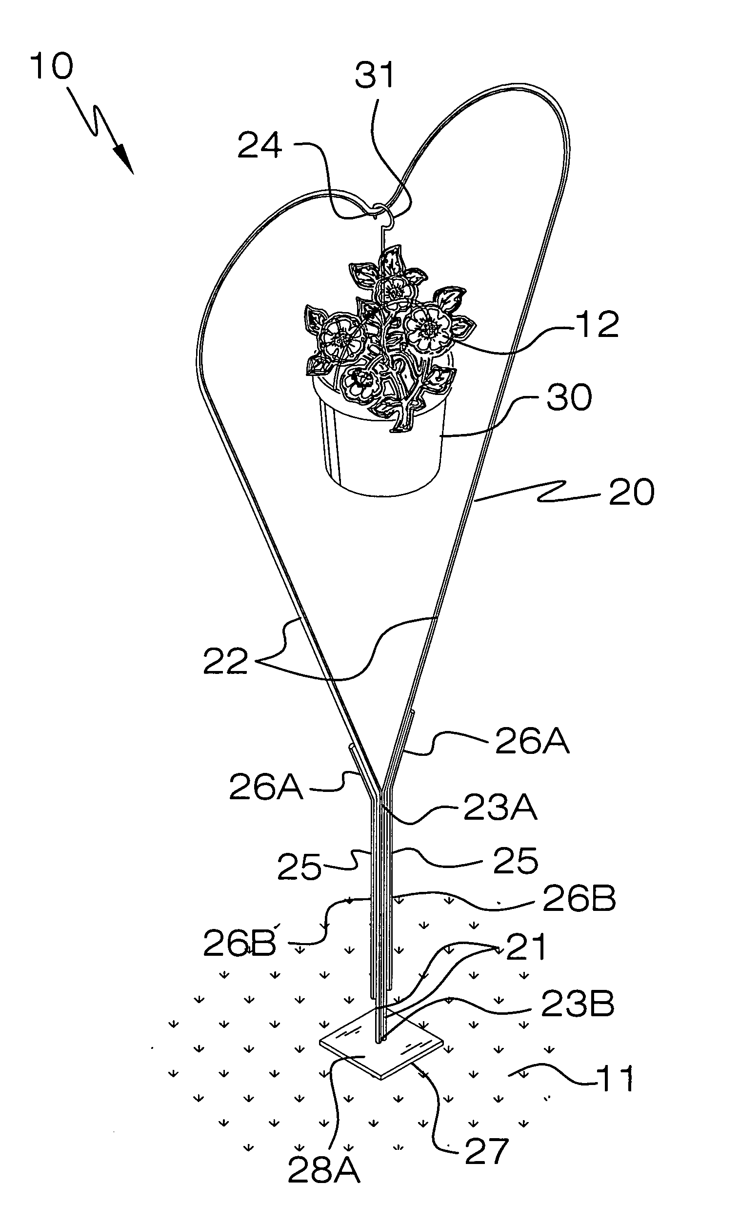
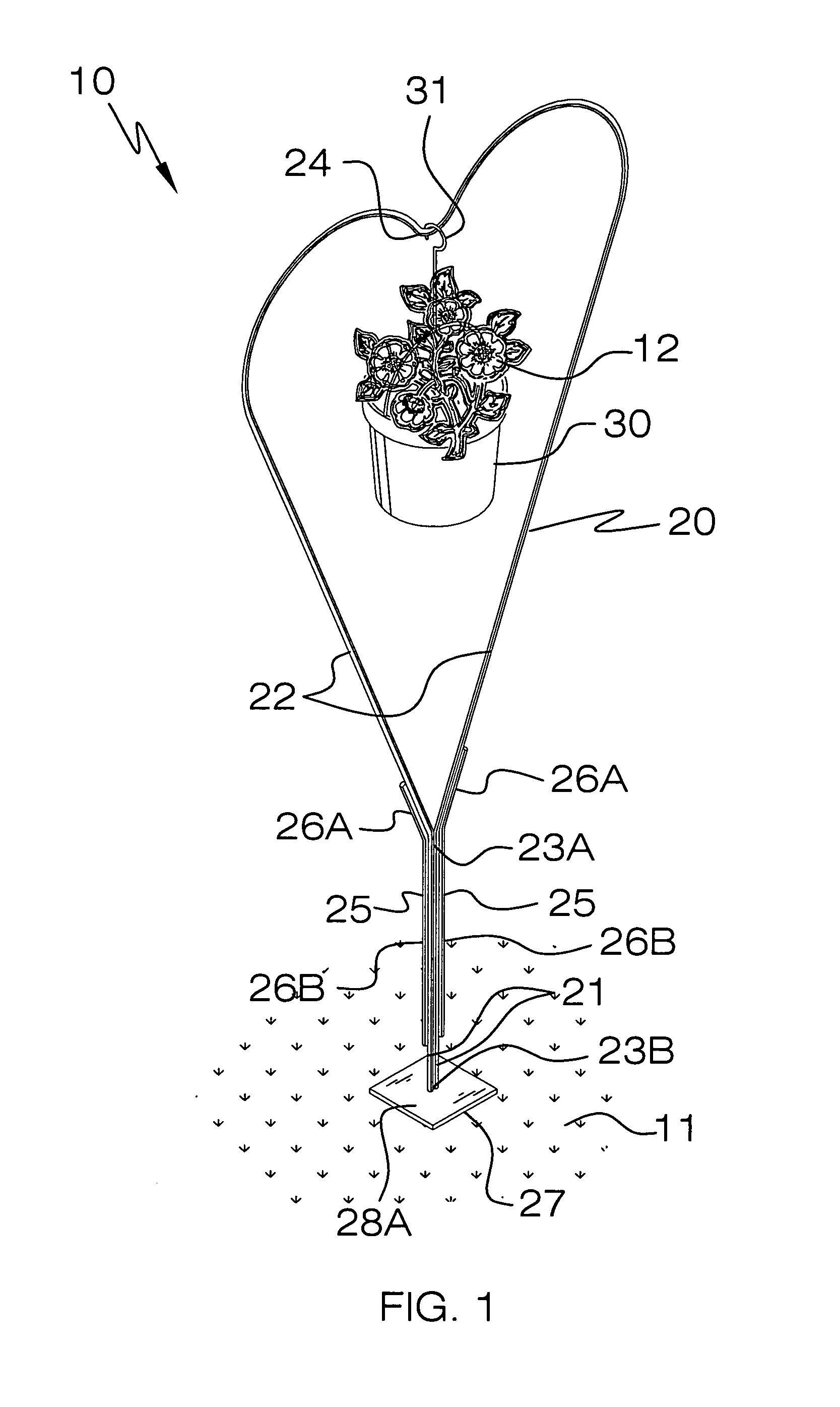
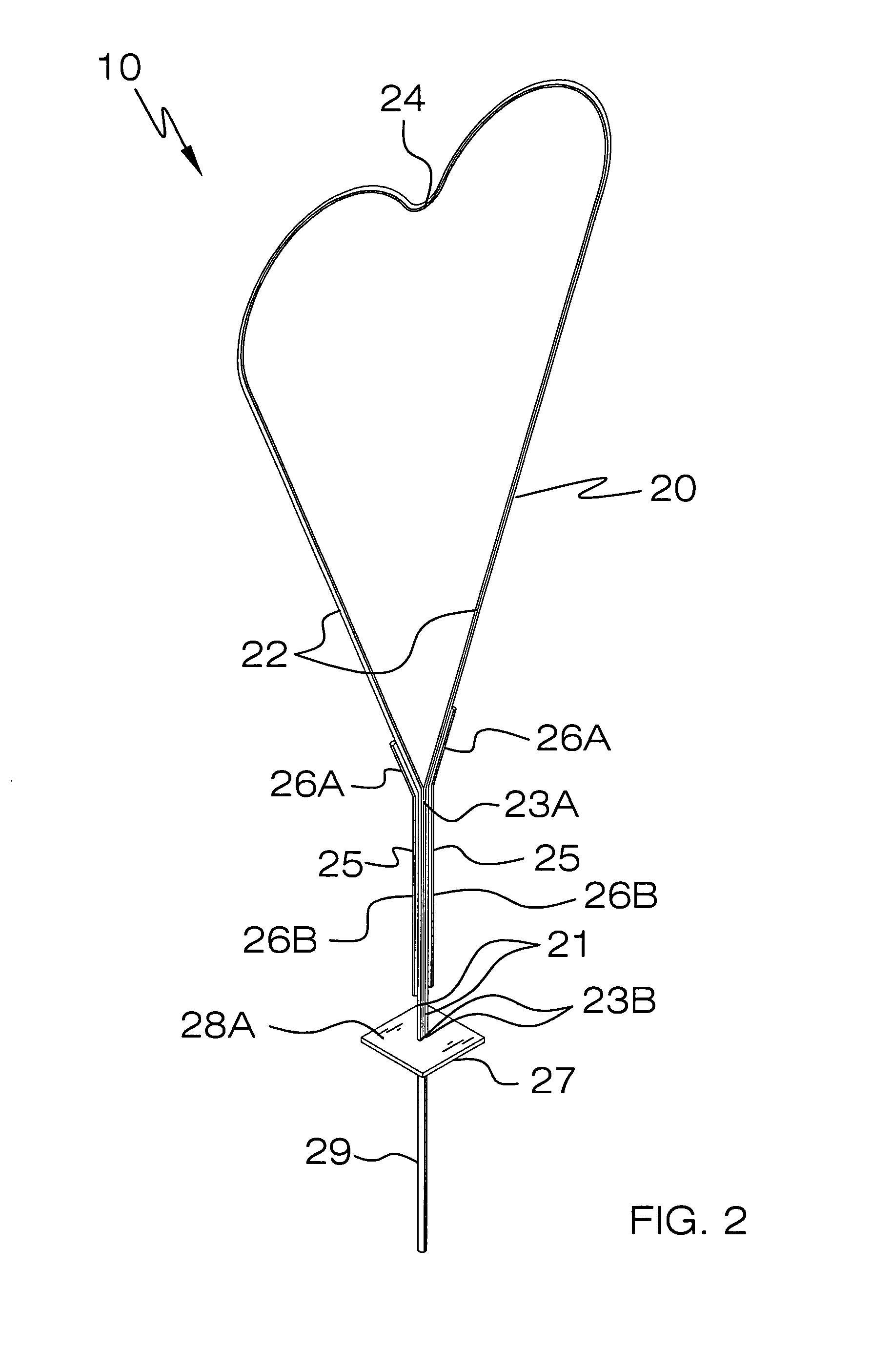
[0013]A pair of coextensively shaped support rods are directly conjoined to the lower end portions and the top portion of the body. Such support rods are coextensively shaped and uniformly confront a longitudinal length of the body. The support rods preferably include monolithically formed upper and lower regions. Such lower regions have longitudinal lengths greater than longitudinal lengths of the upper regions. The upper regions are vertically offset from the lower regions wherein the upper regions flange outwardly and away from a top edge of the lower regions. Such upper regions further preferably maintain continuous and uniform contact with the top portion of the body for advantageously and effectively preventing the body from undesirably bowing outwardly and away from the lower end portions when a plant pot is attached to the top portion of the body. The support rods may be permanently welded to the body.
[0014]A base plate that has planar top and bottom surfaces is directly engaged with a bottom edge of the lower end portions and the ground surface. An anchor rod is directly conjoined to the bottom surface of the base plate and oriented orthogonal thereto. Such an anchor rod extends vertically down and away from the base plate and is coplanar with the lower end portions of the body. The anchor rod is nested below the ground surface for advantageously and effectively maintaining the body at a fixed position during inclement weather conditions. The anchor rod has a diameter greater than a diameter of the lower end portions and the support rods respectively. A plant pot is included that has a hook directly attached thereto. Such a hook is directly and removably attached to the top portion of the body. The base plate may be modified by drilling holes therein to facilitate anchoring the base plate to a concrete surface via conventional fasteners. This would require removal of its ground stakes. Also, small hooks could be added to a perimeter of to allow smaller plants to be hung from the present invention.

Problems solved by technology

Certain flowers, however, only thrive when planted in a highly controlled soil environment, which is usually only attainable when planting the flower in a pot that has predetermined quantities of minerals, vitamins and fertilizer in the soil.
Unfortunately, this example does not readily compensate for instability issues that may arise when the user whishes to only suspend one plant therefrom.
Unfortunately, the mounting means is not sufficient for fixedly securing the apparatus in a ground surface, thus causing the apparatus lean and fall over when uneven amount of weight are distributed thereabout.
Furthermore, the complex design of the apparatus makes production and construction thereof more difficult than needs be.

Method used


Image

  • Self-supporting plant holder
  • Self-supporting plant holder
  • Self-supporting plant holder

Examples


Embodiment Construction

[0022]The present invention will now be described more fully hereinafter with reference to the accompanying drawings, in which a preferred embodiment of the invention is shown. This invention may, however, be embodied in many different forms and should not be construed as limited to the embodiment set forth herein. Rather, this embodiment is provided so that this application will be thorough and complete, and will fully convey the true scope of the invention to those skilled in the art. Like numbers refer to like elements throughout the figures.

[0023]The apparatus of this invention is referred to generally in FIGS. 1–4 by the reference numeral 10 and is intended to provide a self-supporting plant holder. It should be understood that the apparatus 10 may be used to support many different types of plants and should not be limited in use to only supporting flowering plants.

[0024]Referring initially to FIGS. 1 through 4, the apparatus 10 includes a unitary and single body 20 that has di...


PUM


Abstract

An apparatus includes a body that has abutted and rectilinear lower ends that extend upwardly from the ground surface and terminate thereabove. The body has a top portion formed with a top edge of the lower ends and is disposed coplanar therewith. Coextensive support rods are conjoined to the lower ends and the top portion. The support rods are coextensively shaped and confront a length of the body. A base plate is engaged with the lower ends and the ground surface. An anchor rod is conjoined to the base plate and extends vertically down and away therefrom. The anchor rod is nested below the ground surface for maintaining same at a fixed position. The anchor rod has a diameter greater than a diameter of the lower end portions and the support rods respectively. A plant pot has a hook attached thereto that is attachable to the top portion.

Description

CROSS REFERENCE TO RELATED APPLICATIONS[0001]Not applicableSTATEMENT REGARDING FEDERALLY SPONSORED RESEARCH OR DEVELOPMENT[0002]Not ApplicableREFERENCE TO A MICROFICHE APPENDIX[0003]Not ApplicableBACKGROUND OF THE INVENTION[0004]1. Technical Field[0005]This invention relates to plant holders and, more particularly, to a self-supporting plant holder.[0006]2. Prior Art[0007]There are many avid do-it-yourself gardeners and professional landscapers who are constantly striving to obtain the optimum growth from their plants. A particularly attractive addition to any garden is that of brightly and variedly colored flowers. Certain flowers, however, only thrive when planted in a highly controlled soil environment, which is usually only attainable when planting the flower in a pot that has predetermined quantities of minerals, vitamins and fertilizer in the soil. Having a method to aesthetically display such potted plants in an outdoors garden is thus an obvious need of many horticulturists,...

Claims


Application Information

Patent Timeline
IPC IPC(8): A47G7/00A45F3/44
CPCA45F3/44A47G7/042
Inventor DANIELL, ROGER E.
Owner DANIELL ROGER E
Learn More