Method and structure for reducing parasitic influences of deflection devices on spatial light modulators

a technology of spatial light modulator and parasitic influence, which is applied in the field of manufacturing objects, can solve the problems of difficult coating on small components, inability to achieve parasitic influence, so as to reduce parasitic influence and reduce parasitic force

Inactive Publication Date: 2006-11-28
MIRADIA INC
View PDF56 Cites 10 Cited by
  • Summary
  • Abstract
  • Description
  • Claims
  • Application Information

AI Technical Summary

Benefits of technology

[0004]According to the present invention, a method and structure for reducing parasitic influences of deflection devices on spatial light modulators is provided. Merely by way of example, the invention has been applied to a spatial light modulator including a micro-mirror with reduced parasitic forces. The method and structure can be applied to other electro-mechanical technology as well, including actuators and sensors.
[0007]In yet another specific embodiment of the present invention, a method of fabricating contact structures for use in a spatial light modulator is provided. The method comprises providing a first substrate having a device surface and a backside surface and depositing a first layer on the device surface, the first layer having an upper surface opposite the device surface. The method further comprises patterning the first layer to define a plurality of contact structure openings passing through the first layer from the upper surface to the first substrate, depositing a condcutive layer on the upper surface of the first layer, and performing a chemical mechanical polishing step to reduce the thickness of the conductive layer. The method also comprises removing at least a portion of the first layer to expose a plurality of contact structures, joining a second substrate to the device surface of the first substrate to form a bonded substrate structure, and forming a mirror structure in at least one layer of the bonded substrate structure.
[0008]Numerous benefits are achieved using the present invention over conventional techniques. The present invention provides a means to simplify fabrication of spatial light modulator components. Moreover, the present invention provides a flexible design that can be optimized to meet the needs of particular applications. For example, the size and position of landing posts may be modified depending on the design constraints presented by a given application. In addition, the flexibility of design extends to materials optimized for particular applications. In embodiments according to the present invention, complex coatings are not necessary to reduce parasitic forces present in the MEMS. In certain embodiments, the invention also provides a way of operating a MEMS device to overcome stiction forces. Depending upon the embodiment, one or more of these benefits may exist. These and other benefits have been described throughout the present specification and more particularly below.

Problems solved by technology

These parasitic forces may be strong enough to overcome the restoring force, resulting in an undesirable adhesion of the suspended member to the electrode.
Unfortunately, these techniques also have limitations.
For example, some coatings are difficult to deposit on small components and can require complex deposition equipment.
Moreover, complex mechanical structures may have reliability and lifetime concerns.

Method used


Image

  • Method and structure for reducing parasitic influences of deflection devices on spatial light modulators
  • Method and structure for reducing parasitic influences of deflection devices on spatial light modulators
  • Method and structure for reducing parasitic influences of deflection devices on spatial light modulators

Examples


Embodiment Construction

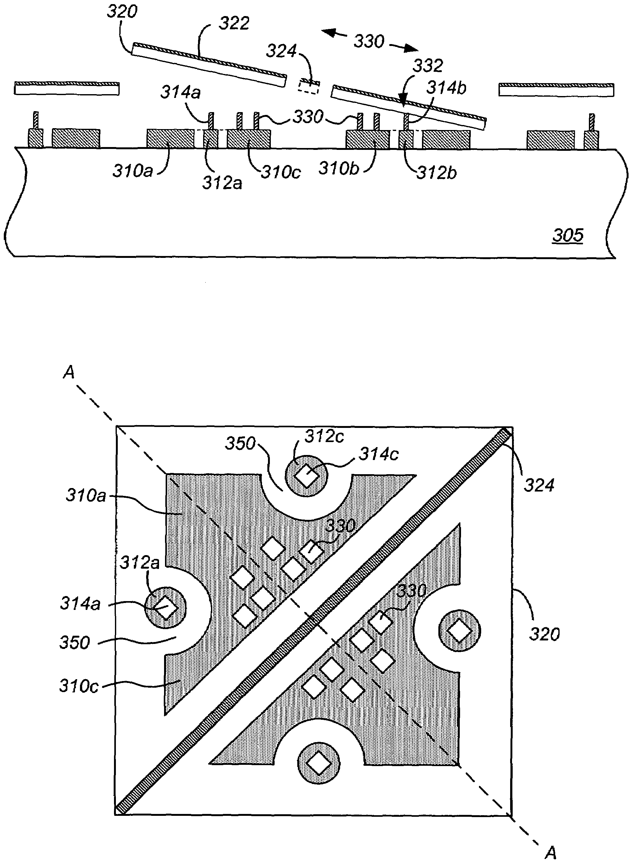
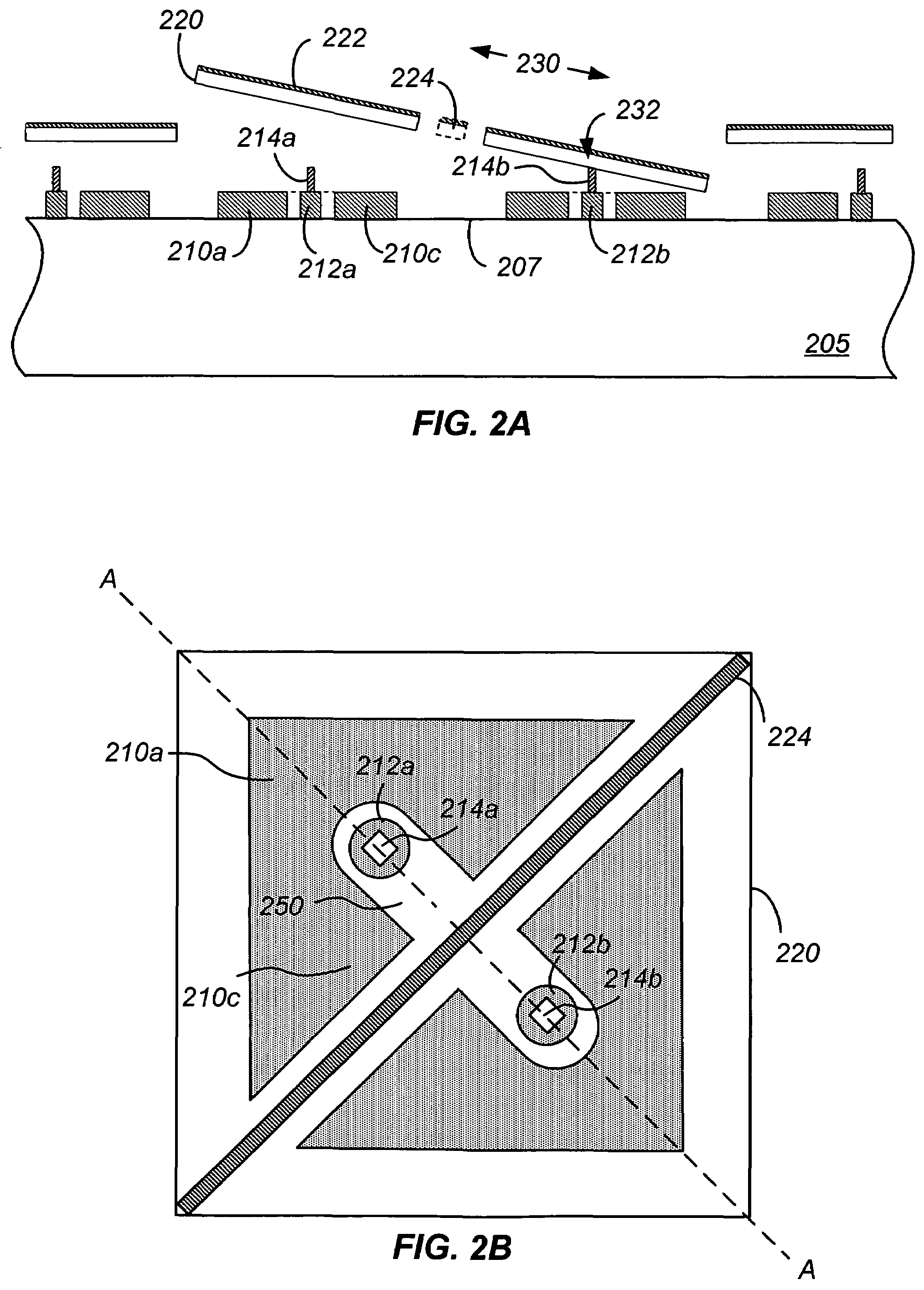
[0016]Embodiments according to the present invention provide a method and structure for reducing parasitic influences of deflection devices on spatial light modulators. Merely by way of example, the invention has been applied to a spatial light modulator including a micro-mirror with reduced parasitic forces. The method and structure can be applied to other electro-mechanical technology as well, including actuators and sensors.

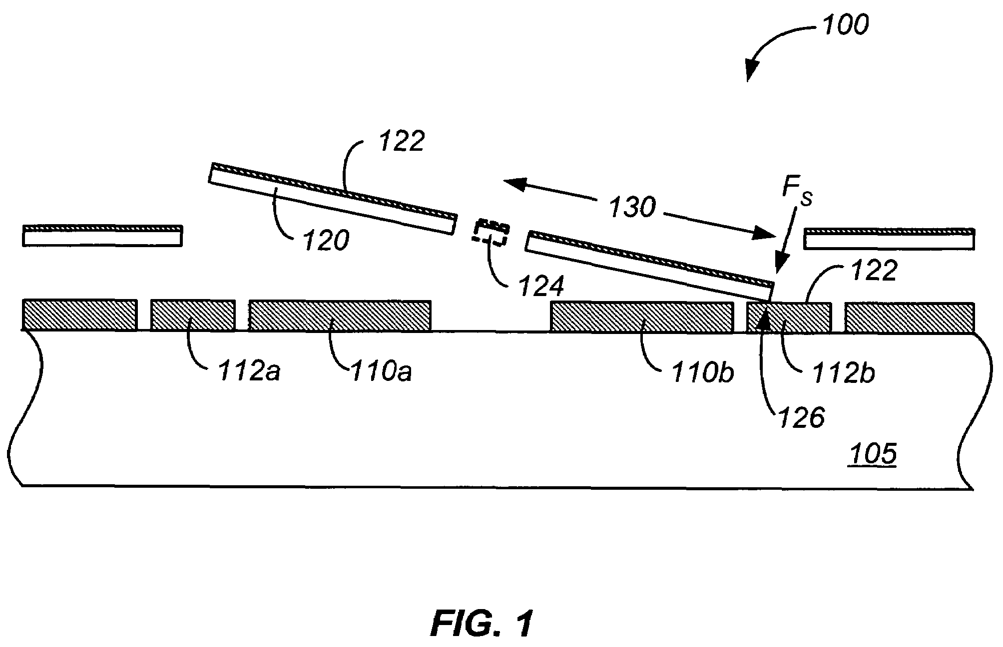
[0017]FIG. 1 is a simplified cross-sectional illustration of a conventional spatial light modulator. Suspended member 120 is suspended at a predetermined height above a substrate 105. Suspended member 120 has a reflective surface 122 coupled to the member. In addition, a torsion spring 124 is coupled to both the suspended member and a support structure (not shown) on substrate 105. In the figure, an electric potential has been applied between electrodes 110 and the suspended member, resulting in tilting of the suspended member in a clockwise direction and plac...


PUM


Abstract

A spatial light modulator is provided. The spatial light modulator includes a first substrate, the first substrate comprising a plurality of electrodes adapted to receive control signals, and a bias grid coupled to the first substrate and electrically isolated from the plurality of electrodes. The spatial light modulator also includes a mirror plate electrically coupled to the bias grid and adapted to rotate from a first orientation to a second orientation in response to the control signals received by the plurality of electrodes. The spatial light modulator further includes a landing post support structure coupled to the first substrate and electrically coupled to the bias grid and a landing post coupled to the landing post support structure. The landing post is electrically coupled to the bias grid and adapted to make contact with the mirror plate positioned at the first orientation.

Description

BACKGROUND OF THE INVENTION[0001]This present invention relates generally to manufacturing objects. More particularly, the invention provides a method and structure for reducing parasitic influences of deflection devices on spatial light modulators. Merely by way of example, the invention has been applied to a spatial light modulator including a micro-mirror with reduced parasitic forces. The method and structure can be applied to other electro-mechanical technology as well, including actuators and sensors.[0002]Micro-electromechanical systems (MEMS) are used in a number of application areas. For example, MEMS have been used in micro-mirror arrays, sensors, and actuators. In some of these applications, a suspended member is attracted to an electrode upon application of an electrical force and restored to an original position by a restoring force. As the suspended member approaches the electrode, surface forces can exert influences on the MEMS. These surface forces are sometimes refe...

Claims


Application Information

Patent Timeline
Patent Type & Authority Patents(United States)
IPC IPC(8): G02B26/00G02B26/08
CPCG02B26/0841
Inventor YANG, XIAO
Owner MIRADIA INC
Why Eureka
Try Eureka