
Two-point modulator comprising a PLL circuit and a simplified digital pre-filtering system

a two-point modulator and digital pre-filtering technology, applied in the field of two-point modulators, can solve the problems of high implementation complexity of such digital and analog filters, corresponding modulation signals are in turn corrupted by the response, etc., and achieve the effect of low implementation complexity

Inactive Publication Date: 2006-11-28
INTEL CORP
View PDF9 Cites 12 Cited by
  • Summary
  • Abstract
  • Description
  • Claims
  • Application Information

AI Technical Summary

Benefits of technology

[0008]It is therefore an object of the invention to create a two-point modulator for phase or frequency modulation with a PLL circuit, in which the filters used for prefiltering the digital and analog modulation signals can have different pulse shapings and at least one of the two filters is intended to have the lowest implementation complexity possible, without significantly altering the two-point modulator's transmission spectrum in the process.
[0011]The digital filter contained in the second circuit path can be produced by a digital filter with a square-wave pulse response on account of the small bandwidth of the closed PLL control loop. Usually, there is not much difference between the transfer functions of a digital filter which is normally used for these purposes and of a digital filter with a square-wave pulse response within the small bandwidth of the PLL control loop. The present invention therefore makes it possible for the complex digital filter used to date, whose pulse response frequently has the shape of a Gaussian curve, to be replaced by a simple digital filter having a square-wave pulse response (square-wave filter), without the possibility of identifying any significant difference in the two-point modulator's transmission spectrum. The first circuit path remains unaffected by this invention.
[0014]In another advantageous refinement of the invention, the amplitude of the pulse response of the digital filter can be controlled using a unit. This allows the amplitude of the digital modulation signal and hence the modulation index to be adjusted in a simple manner if required. By contrast, known two-point modulators with the same filter function for the digital and analog filtering require each filter coefficient to be adjusted individually, or require additional multiplication or division to be carried out with appropriate rounding operations.
[0016]One advantage of the inventive method is the low implementation complexity for the digital filtering. The small bandwidth of the closed PLL control loop means that there is not much difference between the transfer functions of a normally used digital filter, which has the same pulse shape as a filter which is usually used for filtering the analog modulation signal, and of a digital filter with a square-wave pulse response within the PLL control loop's bandwidth. It is therefore not possible to identify any significant difference in the PLL circuit's transmission spectrum.

Problems solved by technology

The analog modulation supplied at the summation point has a high-pass filtering effect on the output of the PLL circuit on account of the closed control loop, which means that the corresponding modulation signal is in turn corrupted by the response.
A drawback of this is the correspondingly high implementation complexity for such digital and analog filters.

Method used


Image

  • Two-point modulator comprising a PLL circuit and a simplified digital pre-filtering system
  • Two-point modulator comprising a PLL circuit and a simplified digital pre-filtering system

Examples


Embodiment Construction

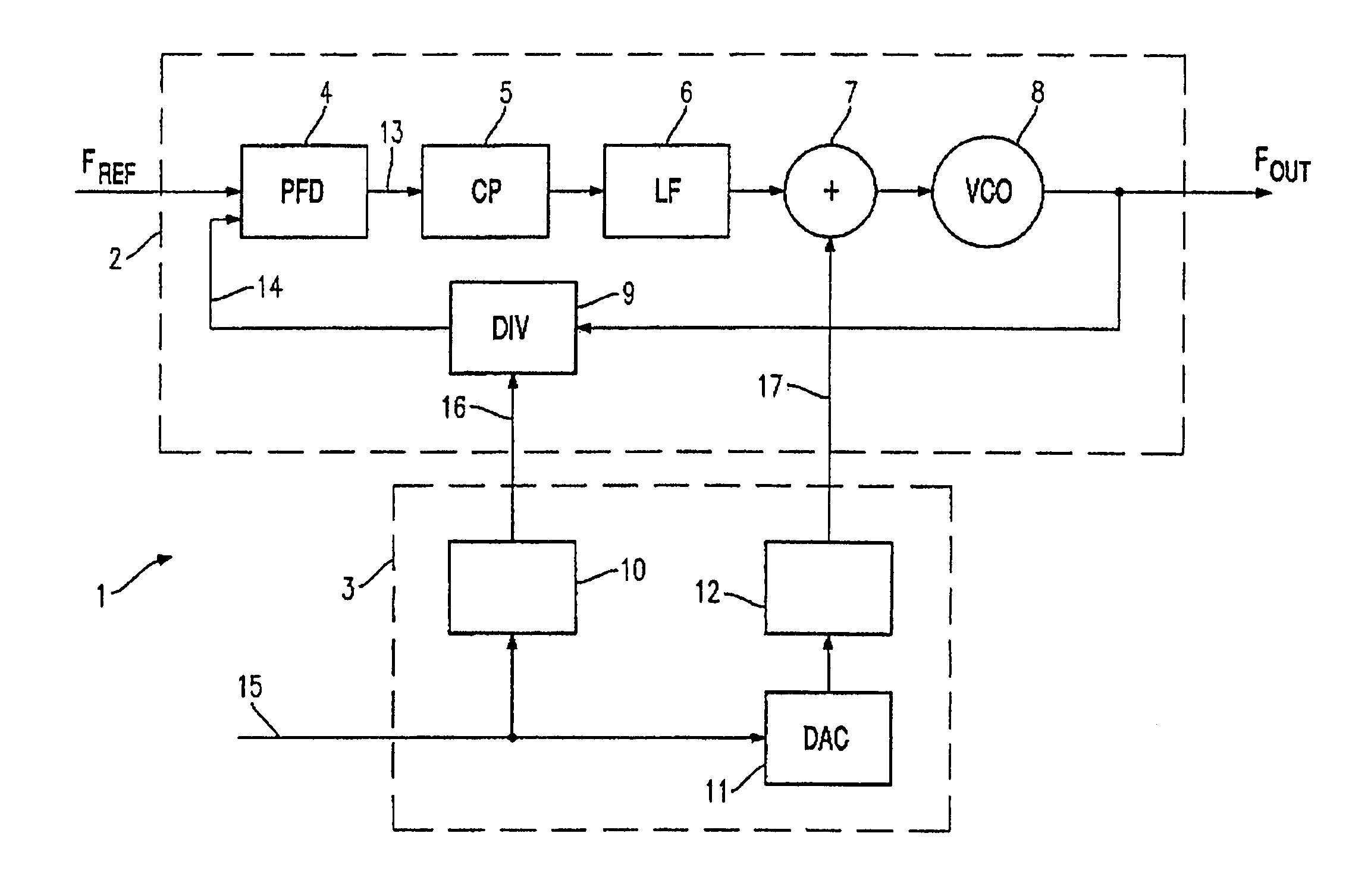
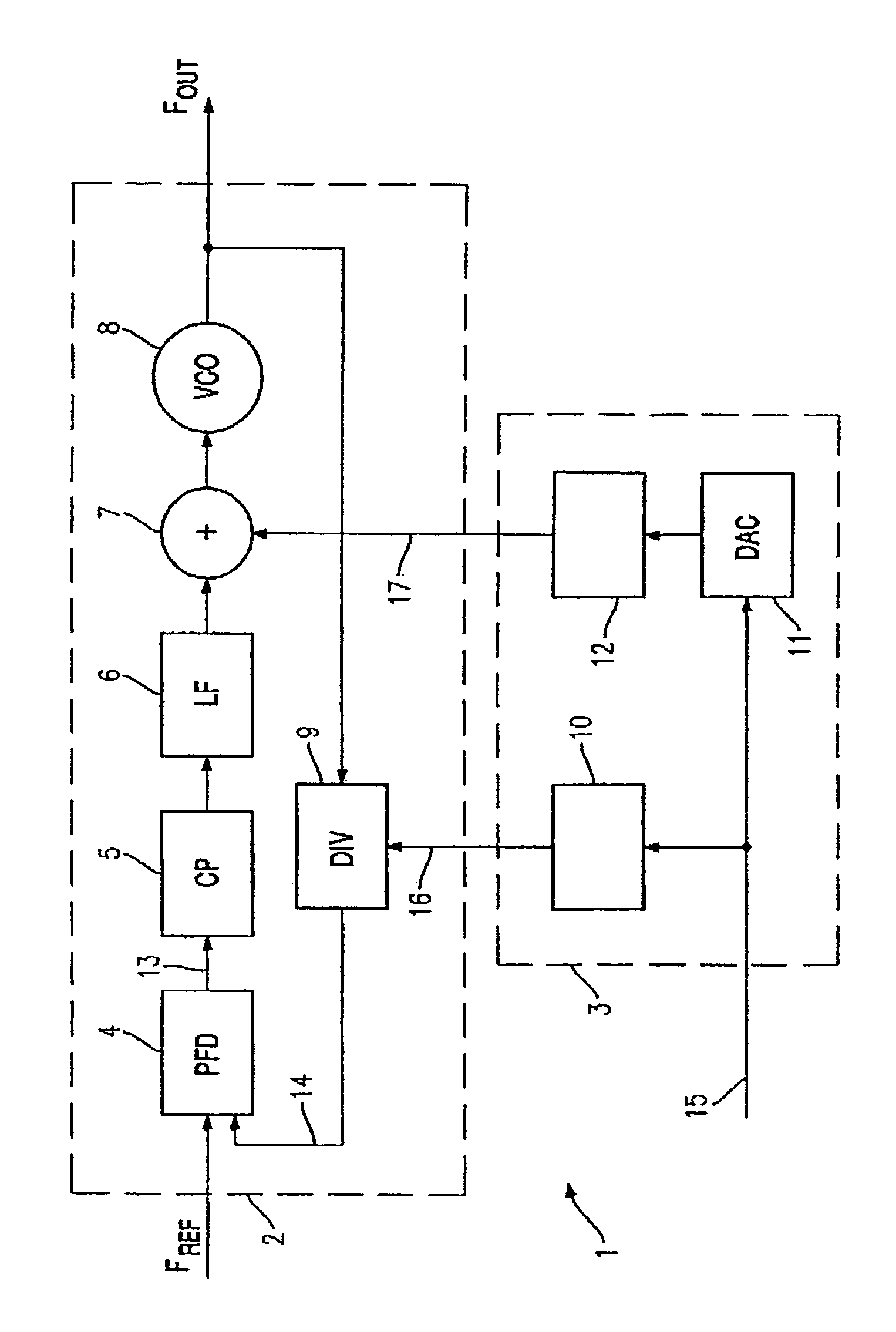
[0018]The invention is explained below by way of example using an exemplary embodiment which is shown in a drawing. The single FIGURE shows a schematic diagram of a two-point modulator with a PLL circuit and a modulation circuit.

[0019]The FIGURE shows a two-point modulator 1 with a PLL circuit 2. The PLL circuit 2 produces an output signal with an output frequency FOUT from an input or reference signal with a reference frequency FREF. The output signal with the output frequency FOUT can be modulated by a digital modulation signal 16 and an analog modulation signal 17.

[0020]Besides the PLL circuit 2, the two-point modulator 1 comprises a modulation circuit 3 which is coupled to the PLL circuit 2 at suitable points and is used to modulate the output signal from the PLL circuit 2.

[0021]The PLL circuit 2 contains a phase detector PFD (Phase Frequency Detector) 4, to whose inputs the reference signals with the reference frequency FREF and a fed back frequency divider signal 14 are suppli...


PUM


Abstract

A two-point modulator includes a PLL circuit and a simplified digital pre-filtering system. The two-point modulator includes a first circuit path for impressing an analog modulation signal into a first point in the PLL circuit, and a second circuit path for impressing a digital modulation signal into a second point in the PLL circuit. The second circuit path actuates a frequency divider in the feedback path in the PLL circuit and contains a digital filter which has a square-wave pulse response.

Description

[0001]This application is a National Stage filing of International Application No. PCT / DE02 / 01914 filed May 24, 2002, which is entitled “Two-Point Modulator Comprising a PLL Circuit and a Simplified Digital Pre-filtering System”, which was not published in English, that claims priority to German Patent Application No. 101 27 612.5 filed on Jun. 7, 2001.FIELD OF THE INVENTION[0002]The invention relates to a two-point modulator for phase or frequency modulation with a PLL circuit which is designed for impressing an analog and a digital modulation signal. In particular, the invention relates to the prefiltering of the digital modulation signal.BACKGROUND OF THE INVENTION[0003]A low-complexity implementation of a transmitter design for transceivers in mobile radio systems is provided by transmitters which have a modulator operating on the basis of the known principle of two-point modulation. In this case, a PLL (Phase Locked Loop) circuit is used as a frequency synthesizer and is used f...

Claims


Application Information

Patent Timeline
IPC IPC(8): H03L7/00H03C1/00H03C3/09
CPCH03C3/0925H03C3/0941H03C3/095
Inventor GREWING, CHRISTIANHAMMES, MARKUSVAN WAASEN, STEFAN
Owner INTEL CORP
Learn More