
Universal valve switch

a universal valve and switch technology, applied in the field of switches, can solve the problems of time-consuming and wasteful procedures, maintenance personnel having to take the extra time to replace the entire valve assembly,

Inactive Publication Date: 2006-11-21
NAT CITY BANK CO
View PDF44 Cites 20 Cited by
  • Summary
  • Abstract
  • Description
  • Claims
  • Application Information

AI Technical Summary

Benefits of technology

Enables efficient maintenance by allowing the valve switch to be universally fitted, reducing maintenance time and costs by allowing the switch to be reset and signaling status changes without replacing the entire valve assembly, while ensuring secure operation.

Problems solved by technology

Accordingly, maintenance personnel must take the extra time to replace the entire valve assembly which is a time consuming and wasteful procedure.

Method used


Image

  • Universal valve switch
  • Universal valve switch
  • Universal valve switch

Examples


Embodiment Construction

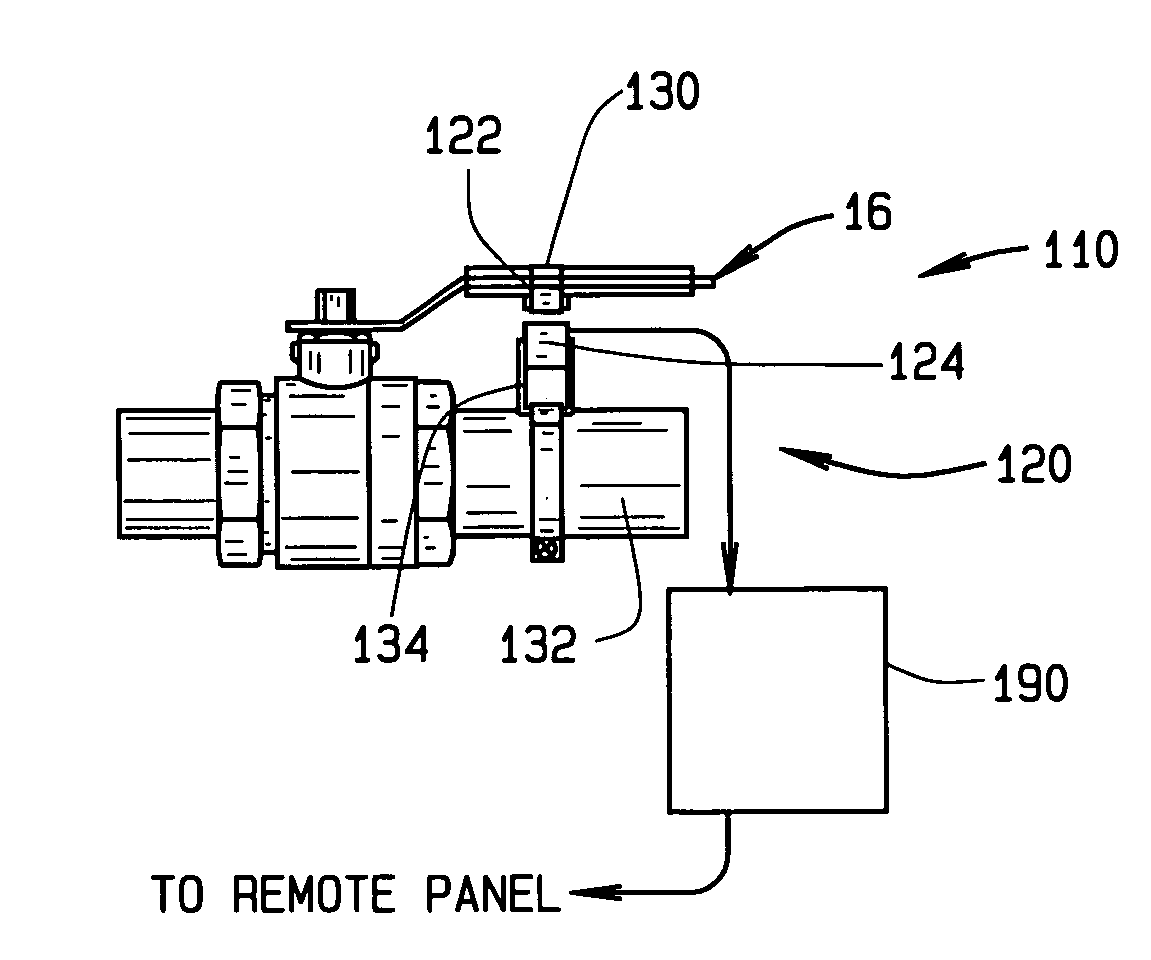
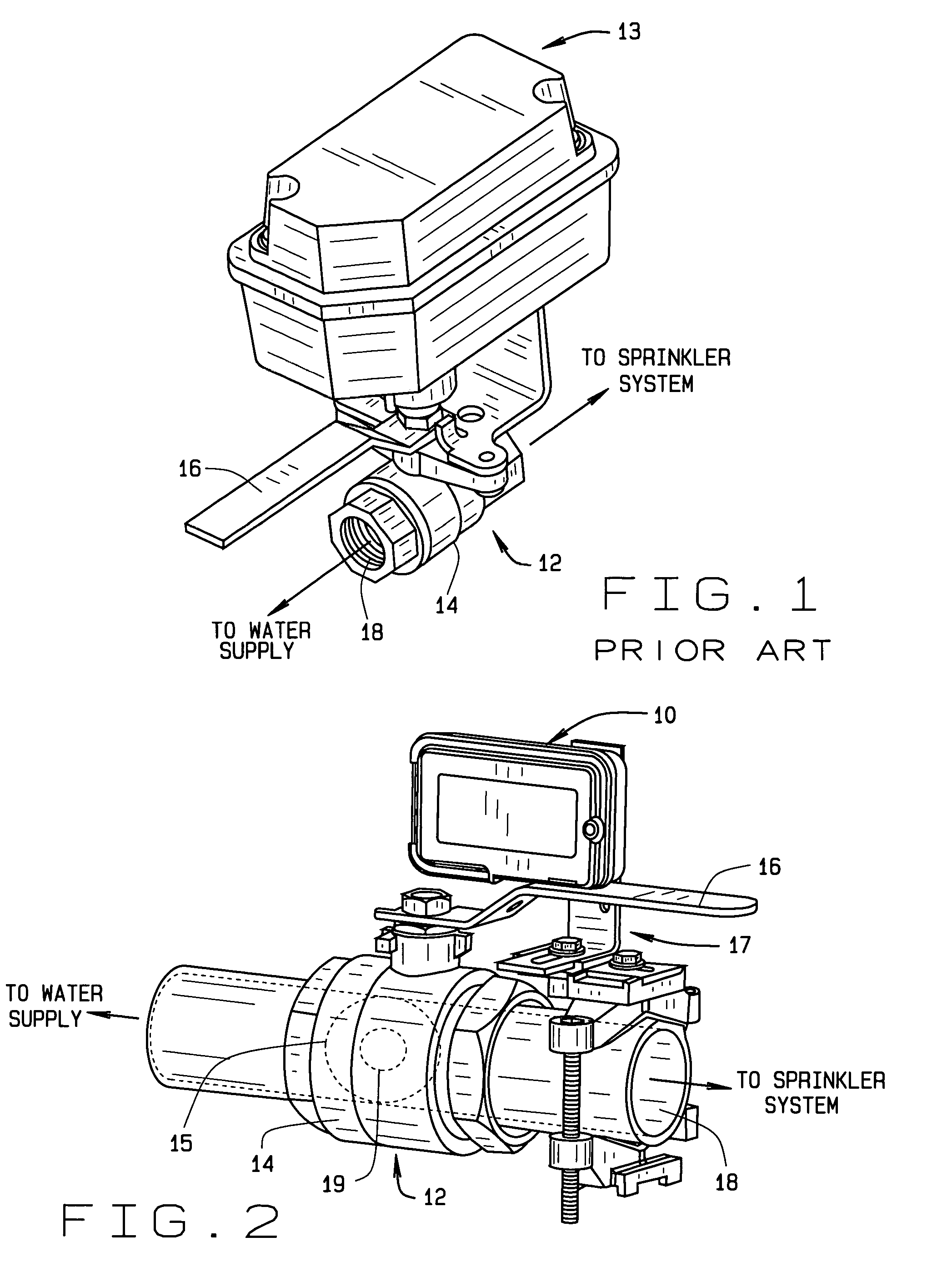
[0037]Referring to the drawings, the preferred embodiment of the universal valve switch used with an existing or new valve assembly 12 is illustrated and generally indicated as 10 in FIG. 2. Valve assembly 12 comprises a valve body 14 defining a conduit 18 (not shown) therethrough for fluid flow communication between a fluid source and a sprinkler system (not shown). A valve member 15 (shown in phantom) having an opening 19 is disposed across conduit 18 and operatively connected to a rotatable lever 16 that is operable between an open, closed and intermediate positions. In the closed position, valve member 15 is positioned such that valve body 14 blocks fluid flow communication through conduit 18, while in the open position, valve member 15 is oriented such that opening 19 is oriented to permit fluid flow communication through conduit 18. In the intermediate position, lever 16 places valve member 15 in a position where limited fluid flow is permitted through conduit 18.

[0038]When pr...


PUM


Abstract

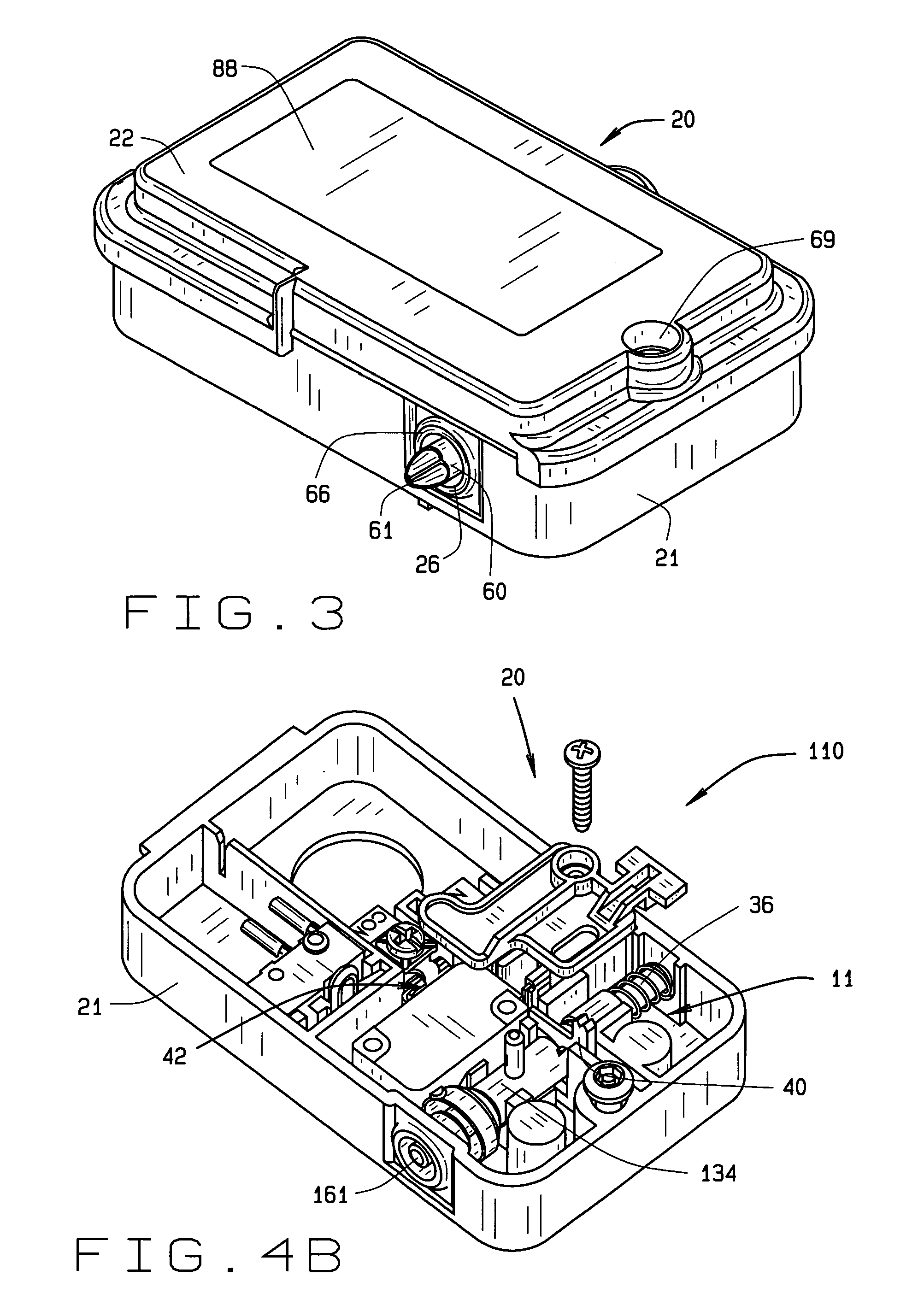
A universal valve switch for signaling the operative state of a valve assembly is disclosed that is attached to the body of the valve assembly using a bracketing arrangement. The valve switch comprises a housing defining a chamber and an aperture formed through the housing that communicates with the chamber. The valve switch may include a contact arrangement having a spring-loaded plunger that is extendable through the aperture with the plunger being operatively associated with the contact arrangement for selectively transmitting a signal to a remote panel whenever the lever is rotated out of contact with the plunger. In other embodiments, the contact arrangement may be replaced with various types of sensor assembly.

Description

CROSS-REFERENCE TO RELATED APPLICATION[0001]This is a divisional application of U.S. Non-Provisional Patent Application entitled “Universal Valve Switch”, Ser. No. 10 / 352,429, filed Jan. 28, 2003 now U.S. Pat. No. 6,945,509, which this application claims benefit and is herein incorporated by reference.BACKGROUND OF THE INVENTION[0002]1. Field of the Invention[0003]The present invention relates to switches, and particularly to a valve switch for a fire suppression system. More specifically, the present invention relates to a valve switch universally fitted to an existing valve assembly.[0004]2. Prior Art[0005]Sprinkler systems for suppressing fires and initiating a fire alarm are well known in the prior art. As shown in FIG. 1, prior art sprinkler systems commonly include a valve assembly 12 interposed along a conduit 18 located between a water supply and the sprinkler system. The valve assembly 12 includes a valve body 14 and a valve member (not shown) which is used to close off the...

Claims


Application Information

Patent Timeline
Patent Type & Authority Patents(United States)
IPC IPC(8): F16K37/00A01G25/16
CPCA01G25/16Y10T137/8242
Inventor ROYSE, DAVID L.
Owner NAT CITY BANK CO
Learn More