Belt device

a belt and belt technology, applied in the field of belt devices, can solve problems such as significant belt meandering, and achieve the effect of preventing meandering and simple configuration

Active Publication Date: 2006-11-14
KYOCERA DOCUMENT SOLUTIONS INC
View PDF6 Cites 23 Cited by
  • Summary
  • Abstract
  • Description
  • Claims
  • Application Information

AI Technical Summary

Benefits of technology

[0012]In this device the driven roller is formed in a so-called crown shape. It is the general nature of belts to be inclined in the direction where belt tension is stronger, that is, the direction with the greater roller contact pressure. Thus, when belt meandering occurs while the belt is moving, and the belt becomes inclined toward either the left or right side, if the driven roller is formed in a crown shape, the belt will naturally return to the center because of the large contact pressure at the roller center, thereby preventing meandering.
[0013]In the present invention, pulleys are provided on both ends of the driven roller for the belt, and are caused to engage with ribs provided on the edges of both sides of the belt, enabling belt meandering prevention with a simple configuration.

Problems solved by technology

However, if because of a difference in perimeter length of the two ends of the belt, there is a large difference in peripheral velocity in the belt width direction, there will be significant belt meandering and the ribs may ride up on the rollers.

Method used


Image

  • Belt device
  • Belt device
  • Belt device

Examples


Embodiment Construction

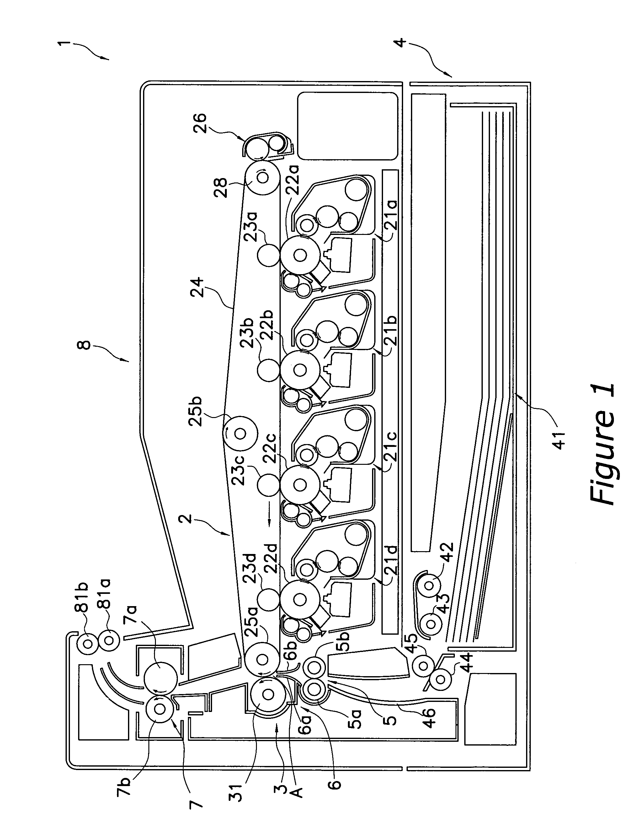
[0018]FIG. 1 is a diagram showing the constitution of the primary portions of a tandem color printer 1 using an embodiment of the present invention. The color printer 1 has an image forming unit 2 that forms a color image, a transfer unit 3 that transfers a toner image formed by the image forming unit 2 to a transfer material, a sheet feed unit 4 that supplies the transfer material, a resist roller unit 5 that synchronizes the transfer material transport and image formation, a transfer material transport guide mechanism 6 that guides transfer material that has reached the resist roller unit 5 to a transfer position, a fuser unit 7 that fuses the toner image transferred to the transfer material, and an output unit 8 that outputs the transfer material.

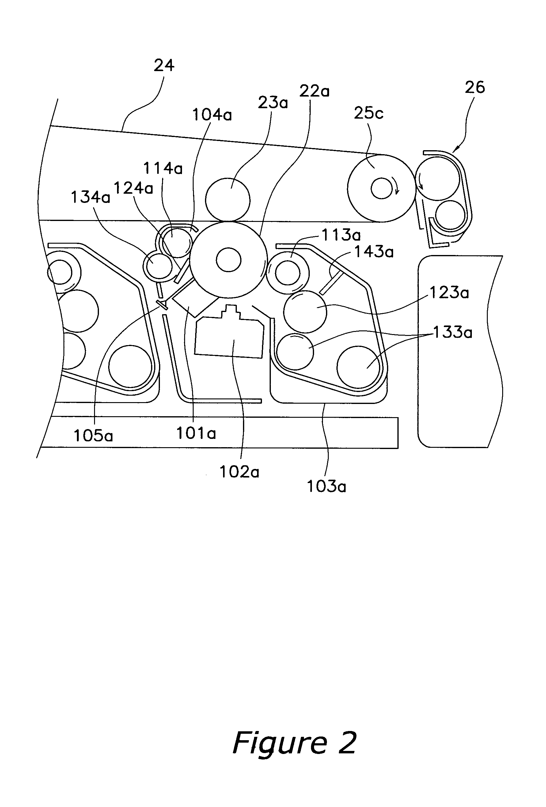
[0019]The image forming unit 2 is positioned roughly at the center of the color printer, and comprises, corresponding to the four colors of black, yellow, cyan and magenta, four process units 21a, 21b, 21c, 21d, four photosensitive drums...


PUM


Abstract

Pulleys 29a, 29b are provided on both ends of the driven roller 28 as separate components from the driven roller 28, and on both edges in the width direction of the transfer belt 24, ribs 24a, 24b that can be engaged with the outer sides in the axial direction of the pulleys 29a, 29b are provided. If the transfer belt 24 becomes inclined to the left side during movement, the rib 24a on the right edge of the transfer belt 24 will be restricted by the outer side in the axial direction of the pulley 29a provided on the right side end of the driven roller 28, thereby correcting meandering to the left at the position of the driven roller 28.

Description

FIELD OF THE INVENTION[0001]The present invention relates to a belt device, and more particularly to a meandering prevention device of an image forming device transfer belt.BACKGROUND INFORMATION[0002]For image forming devices, particularly color photocopiers, color printers and other color image forming devices, multistep drum types (tandem type) capable of higher speed processing than a single drum type device are becoming the mainstream. In a tandem color image forming device, image forming units, for example, magenta, yellow, cyan and black, are arranged by color in the paper transport direction, and a color toner image is sequentially formed by the image forming units of each color.[0003]The image forming units of each color are arranged so as to face a transfer belt serving as an image support body, and the toner image sequentially formed by the image forming units of each color is transferred to the transfer belt by first transfer means. The transfer belt is endlessly wound o...

Claims


Application Information

Patent Timeline
Patent Type & Authority Patents(United States)
IPC IPC(8): G03G15/00
CPCG03G15/1605G03G2215/00151G03G2215/0132G03G15/1615
Inventor MURASE, KOJI
Owner KYOCERA DOCUMENT SOLUTIONS INC
Why Eureka
Try Eureka