Method and equipment for identifying a logical channel

a logical channel and equipment technology, applied in the field of mobile communication systems, can solve the problems of reducing data transmission capacity, traffic channel blocks being lost, and the most difficult to distinguish training sequences, and achieve the effect of improving the capacity of the receiver

Inactive Publication Date: 2006-11-07
CASSIDIAN FINLAND
View PDF19 Cites 24 Cited by
  • Summary
  • Abstract
  • Description
  • Claims
  • Application Information

AI Technical Summary

Benefits of technology

[0011]The method and system of the invention considerably improve the capacity of a receiver in a mobile communications system because a significant portion of misinterpretations relating to the logical channel are left out.

Problems solved by technology

In circumstances where reception is subject to fading and noise, it has proved to be most difficult to distinguish training sequences, and thus logical channels relating to a time slot, from one another.
If a training sequence TS1 is by mistake interpreted as a training sequence TR2, the receiver concludes that a signalling message is concerned, which causes traffic channel blocks to be lost and decreases data transmission capacity.
The possibility that a logical channel can be misinterpreted in this way is most disadvantageous for the operation of the system.
Errors in interpretations are particularly problematic in channels in which bit error ratio should be very small to support efficient channel coding.

Method used


Image

  • Method and equipment for identifying a logical channel
  • Method and equipment for identifying a logical channel
  • Method and equipment for identifying a logical channel

Examples


Embodiment Construction

[0019]In the following the invention will be described as applied to the TETRA system (TErrestrial Trunked RAdio), the invention not being restricted to the system or to the names of the structural parts. The solution of the invention can also be applied to other digital radio systems in which a logical channel relating to a time slot is not always unambiguously apparent from the frame structure used.

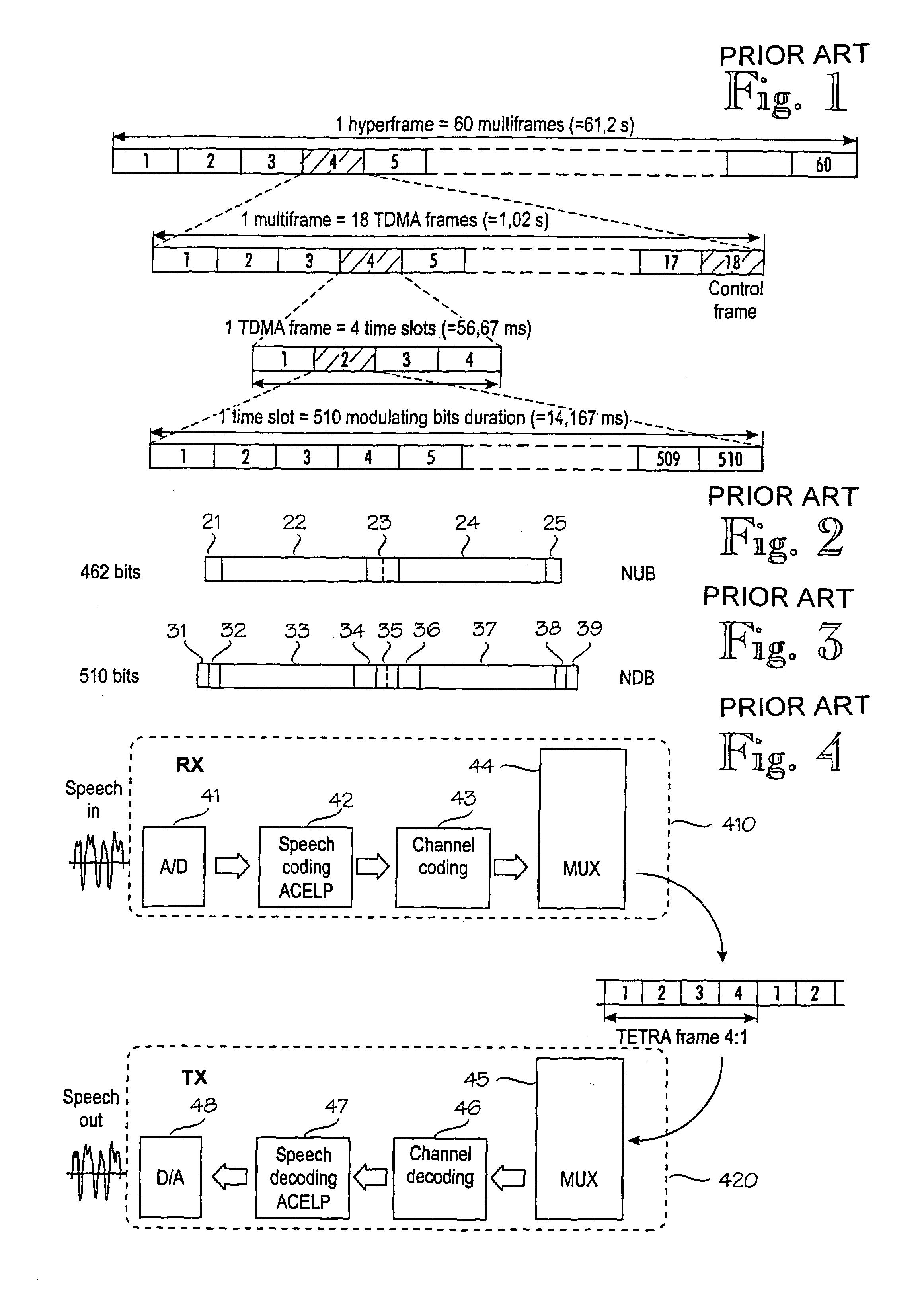
[0020]FIG. 1 shows a frame structure in the TETRA system. In the TETRA system a physical channel is comprised of one TDMA time slot, a TETRA frame comprising a total of four time slots. One time slot comprises 510 bits (255 modulation symbols) and its duration is 14.167 ms. A TETRA superframe, the duration of which is 1.02 s, comprises 18 TETRA frames, the 18th frame of the superframe being reserved as a control frame. A TETRA hyperframe comprises 60 TETRA superframes and its duration is 61.2 s.

[0021]A burst is a sequence modulated by carrier data flow and it describes the physical cont...


PUM


Abstract

A method and an equipment implementing the method that allow a logical channel, to which a received burst relates, to be identified with certainty also in demanding operational circumstances. A logical channel relating to a time slot is identified by applying channel decoding. The identification can be a primary identification or a confirming identification taking place after a primary identifier the time slot comprises, preferably a bit map, has been interpreted. If identification based on channel decoding contradicts identification based on the bit map, a receiver can be arranged to indicate logical channel information on the basis of the channel decoding, for instance by changing the bit map, when selected criteria are met, to a bit map conforming to the logical channel identified on the basis of the channel decoding. The invention significantly improves the performance of a receiver of a mobile communications system because a considerable part of misinterpretations relating to the logical channel are avoided.

Description

BACKGROUND OF THE INVENTION[0001]The invention relates to mobile communications systems and particularly to a method and equipment for identifying a logical channel in a radio frame part which may comprise information of one or more logical channels, channel decoding of the information being possible by means of channel decoding methods relating to the different logical channels.[0002]In digital radio systems a physical channel provides a link at the interface between a subscriber terminal and a network. A physical channel substantially comprises a frame part of a selected multiple access technique, the frame part being allocated to data transmission between a particular subscriber terminal and the network. A physical channel can therefore comprise for instance one or more TDMA frame time slots arranged at a specific frequency range, or frame parts separated by means of a CDMA frame code.[0003]Physical channels are utilized by means of various multiplexing techniques whereby logical...

Claims


Application Information

Patent Timeline
Patent Type & Authority Patents(United States)
IPC IPC(8): H04J3/00H04J3/12H04L1/00
CPCH04L1/0046H04L1/0061
Inventor PUHAKAINEN, PEKKAVIERO, TIMO
Owner CASSIDIAN FINLAND
Why Eureka
Try Eureka