Atmospheric stabilizer filter and method

a stabilizer filter and atmospheric technology, applied in the field of optical filters, can solve the problems of reducing the size of adaptive optics, increasing the light but not proportionally improving the resolution of the optical system, and affecting the ability of amateur astronomical observers to fix etc., to achieve the effect of convenient attachment to optical devices or telescopes

Inactive Publication Date: 2006-11-07
BARZIZA SAMUEL W
View PDF2 Cites 1 Cited by
  • Summary
  • Abstract
  • Description
  • Claims
  • Application Information

AI Technical Summary

Benefits of technology

[0015]Alternatively, the optical filter can provide photoetched cross-hatched opaque lines which are between 0.4 and 0.6 microns and thereby providing cells with a width of each translucent cell between 5 to 7 microns.

Problems solved by technology

The larger aperture will collect more light but will not proportionately improve the resolution of the optical system.
Adaptive optics reduces the sizes of the isoplanar mirror assemblies and then coordinates them based upon atmospheric turbulence, but is both complicated and expensive and beyond the budget of the amateur astronomical observer.
Substantial and expensive equipment support equipment and technician time is required for either type of stabilization system.
Maintenance of such systems often interferes with observation time, limiting and therefore decreasing time-critical investigations.
Currently, there is no known device, passive in nature (i.e. having no moving parts, and no electrical apparatus) that attaches to a telescope and suppresses atmospheric turbulence.
Both adaptive optics and active optics involve considerable technical sophistication and are limited to small areas of the sky.

Method used


Image

  • Atmospheric stabilizer filter and method
  • Atmospheric stabilizer filter and method
  • Atmospheric stabilizer filter and method

Examples


Embodiment Construction

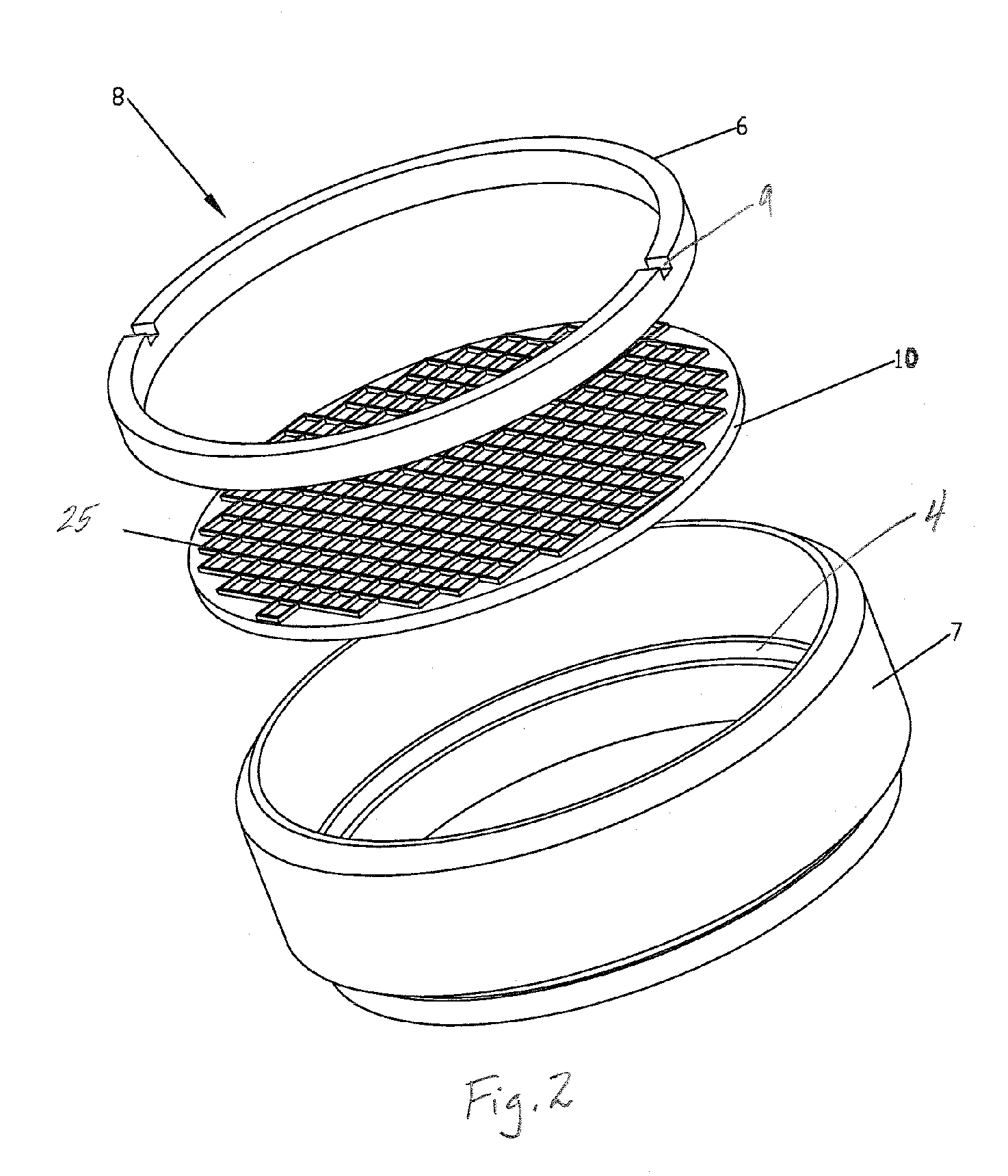
[0021]As shown in FIG. 1, the Atmospheric Stabilizer Filter plate 10 is fashioned from a quartz substrate 20. Lines 25 are etched on an exterior surface of the quartz substrate 20, such as by photoetching. In this embodiment, the lines are etched to form a screen with the line width 4 of approximately 0.5 micron (0.5×10⁻⁶ meters) and providing a space 3 between each adjacent line of approximately 6 microns (6.0×10⁻⁶ meters). The ratio of line spacing to line width is believed to be optimal if kept in the 6 to 1 to a 12 to 1 ratio. The spaces 5 between adjacent perpendicular lines permit the transmission of coherent essentially planar wave fronts through the filter. It is believed that other geometric designs such as hexagonal openings between adjacent lines or circular openings can be substituted on the existing plate design without departing from the spirit of this invention.

[0022]As shown in FIG. 2, retainer ring 6 used to hold the Atmospheric Stabilizer Filter assembly 8 in the m...


PUM


Abstract

A diffracting optical filter for use with telescopes provides a plurality of cells separated by opaque lines on an translucent substrate, the spacing of the cells proportionally spaced to match the Airy disk of a specific optical system for the telescope to aid observation through a turbulent atmosphere.

Description

[0001]This application claims the benefit of prior provisional application U.S. Ser. No. 60 / 521,143 filed Feb. 26, 2004.BACKGROUND OF INVENTION[0002]This present invention relates to an optical filter for use with telescopes; specifically to a diffracting filter composed of a plurality of spaced translucent cells separated from each other by a thin opaque border in which the spacing of the cells is proportional to the Airy disk of a specific optical system for the telescope to aid observation through a turbulent atmosphere.[0003]Turbulent atmospheric phenomena limit the visual range of observations in the 380 nm to 750 nm wavelength (λ) range of visible light. All forms of telescopic astronomical investigation will benefit from such a device; ranging from casual visual observations to in-depth detailed scientific imaging, spectroscopic, photometric, astrometric, and interferometric investigations.[0004]Driven by the thermal energy of the sun, the motion of the earth's atmosphere cha...

Claims


Application Information

Patent Timeline
Patent Type & Authority Patents(United States)
IPC IPC(8): G02B23/00G02B5/18G02B5/20G02B27/42
CPCG02B5/203G02B23/00G02B27/42G02B27/4205
Inventor BARZIZA, SAMUEL W.
Owner BARZIZA SAMUEL W
Why Eureka
Try Eureka