
Device for determining fuel quality and corresponding method

a technology for determining the quality of fuel and the corresponding method, which is applied in the direction of machines/engines, electric control, instruments, etc., can solve the problems of large correction, low cost, and relatively imprecise amount calculation, and achieve the effect of low cos

Inactive Publication Date: 2006-10-31
VITESCO TECH GERMANY GMBH
View PDF8 Cites 24 Cited by
  • Summary
  • Abstract
  • Description
  • Claims
  • Application Information

AI Technical Summary

Benefits of technology

The invention is about a device and method for determining the quality of fuel in an injection system, based on the gas emission behavior of the fuel. The device measures the pressure and temperature in the fuel container, and uses these measurements to calculate a quality value that represents the fuel quality. The method is cost-effective because existing injection systems already have a temperature sensor. The technical effect of the invention is to provide a simple and effective way to assess the quality of fuel in an injection system.

Problems solved by technology

The correction amount is calculated relatively imprecisely, however, so that sometimes the correction proves too great.
In particular, given a “poor start”, the injection period is changed so as to make the fuel-air mixture richer, which means that the fuel-air mixture may be too rich after filling up with a very good quality fuel.
As a result, the internal combustion engine starts badly or not at all.
Another disadvantage of this method for determining the fuel quality is the relatively low accuracy, because the increase in speed when starting the internal combustion engine does not depend solely on the fuel quality but is also affected by other parameters such as the internal friction of the internal combustion engine.
This method has the disadvantage that it only works when the lambda control system is enabled.
This is specifically not the case, however, when the internal combustion engine is cold.
The disadvantage of these known methods for determining the fuel quality, however, is that they are coupled with the combustion process and hence may also be affected by other parameters.

Method used


Image

  • Device for determining fuel quality and corresponding method
  • Device for determining fuel quality and corresponding method
  • Device for determining fuel quality and corresponding method

Examples


Embodiment Construction

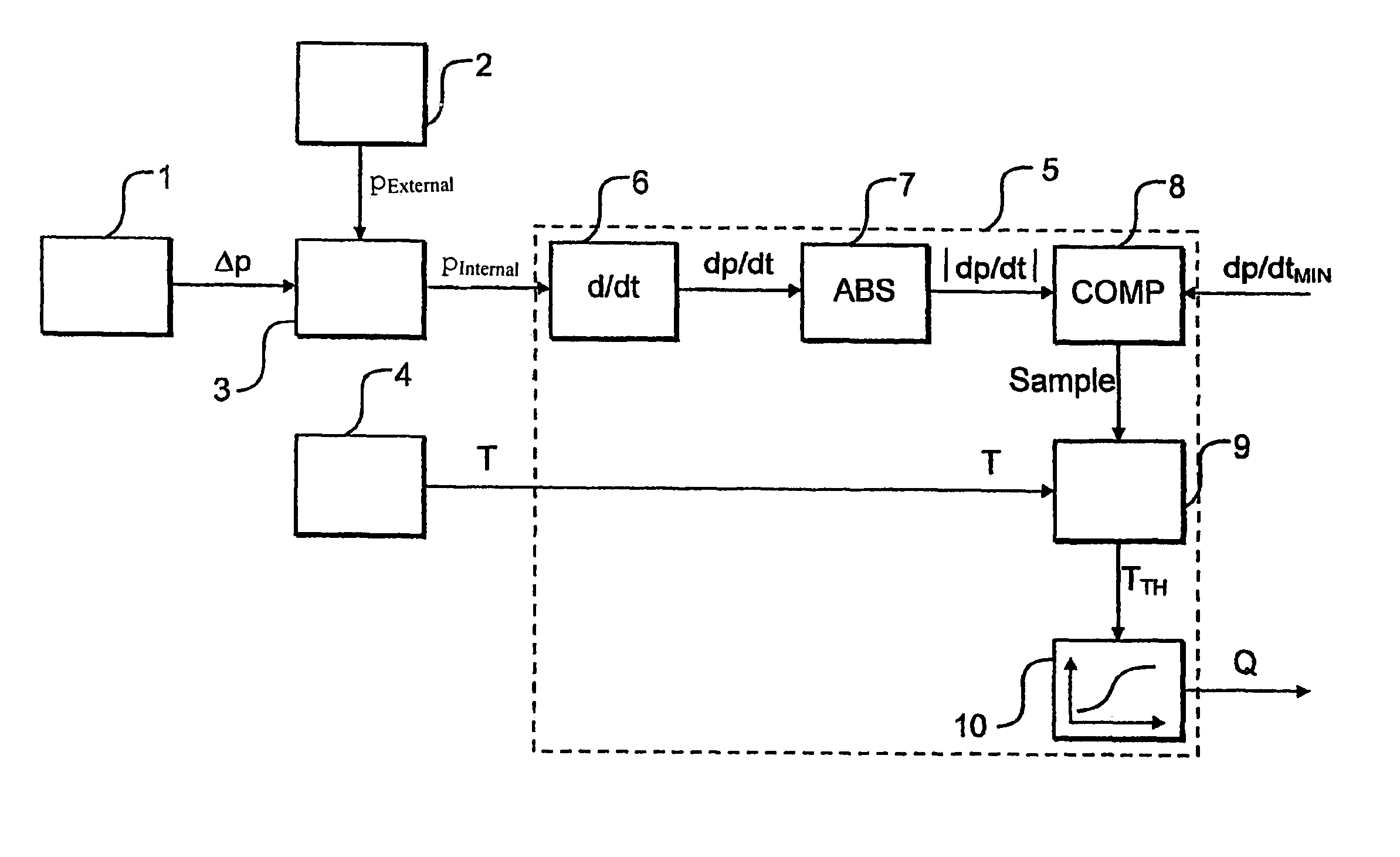
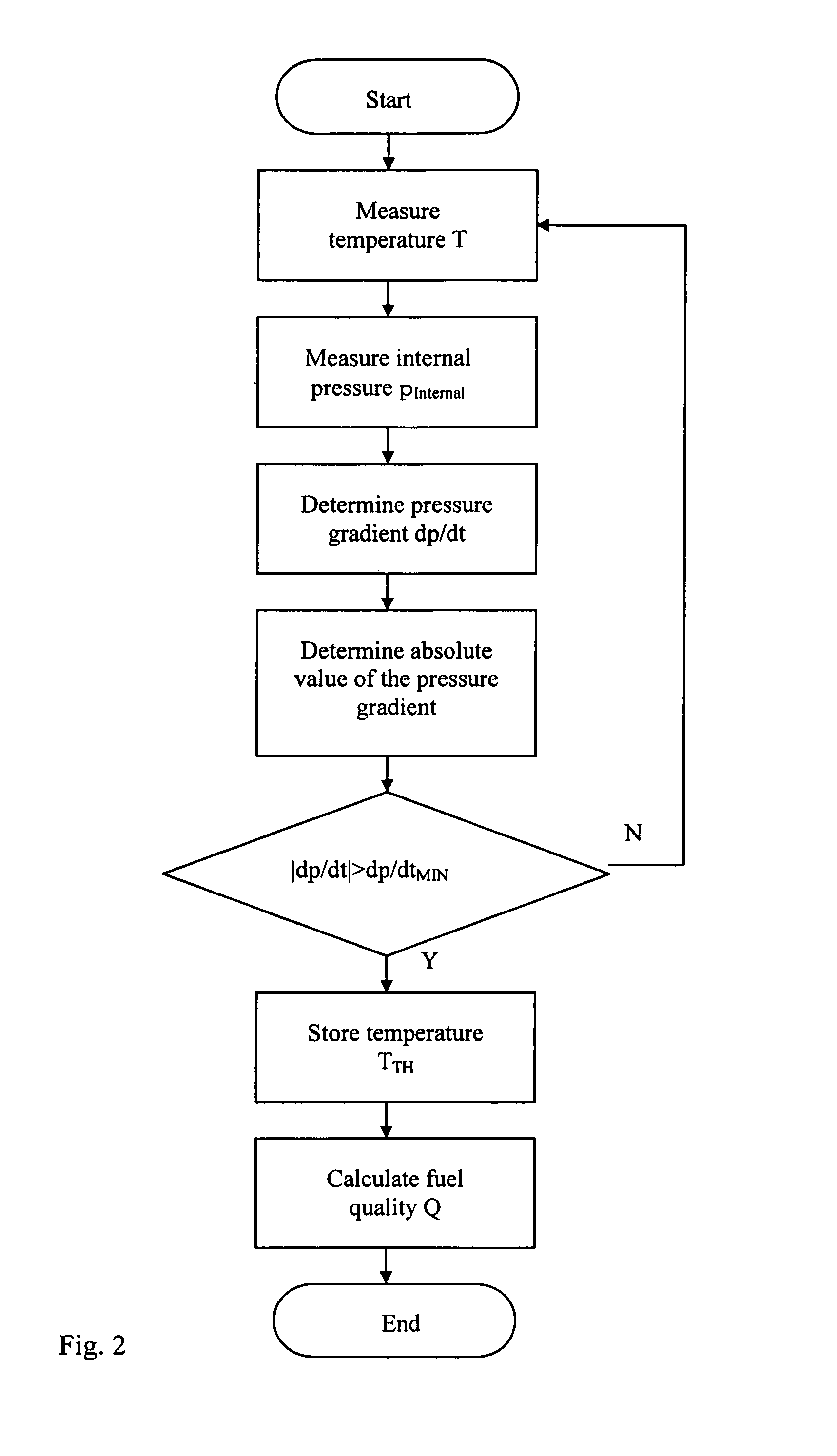
[0028]The device according to the invention shown in FIG. 1 is used for determining the quality of the fuel in a fuel container of an internal combustion engine and enables the determined fuel quality to be taken into account when running the internal combustion engine, for example by controlling an injection system accordingly.

[0029]The determination of the fuel quality according to the invention is based on the knowledge that the gas emission behavior of the fuel depends on the fuel quality, because long-chain hydrocarbons have a weaker gas emission than short-chain hydrocarbons. For a standard composition of the fuel containing a defined proportion of long-chain and short-chain hydrocarbons, the fuel therefore has a defined gas emission behavior, while deviations in the fuel composition from the standard are associated with a modified gas emission behavior.

[0030]The gas emission behavior of the fuel is in this case measured on the basis of the fuel held in the fuel container, the...


PUM


Abstract

The invention relates to a device for determining the quality of fuel for an internal combustion engine, comprising a pressure sensor (1) for determining the pressure (p) inside a fuel tank and / or comprising a temperature sensor (4) for determining the temperature (T) inside a fuel tank. According to the invention, an evaluation unit (5) is provided for determining a quality value (Q), which depicts die quality of the fuel, based on the temperature (T) and / or the pressure (p) inside the fuel tank. Said evaluation unit is connected on the input side to the pressure sensor (1) and / or to the temperature sensor (4).

Description

CLAIM FOR PRIORITY[0001]This application is a national stage of PCT / DE03 / 01168, published in the German language on Apr. 9, 2003, which claims the benefit of priority to German Application No. DE 102 17 379.6, filed on Apr. 18, 2002.TECHNICAL FIELD OF THE INVENTION[0002]The invention relates to a device for determining the quality of fuel for an internal combustion engine.BACKGROUND OF THE INVENTION[0003]The quality of the fuel used to drive internal combustion engines may be subject to manufacturing tolerances, for example the fuel may contain varying proportions of long-chain hydrocarbons.[0004]It is therefore a well-known procedure to determine the quality of the fuel used and to take this into account in the fuel injection process in order to compensate for the quality variations as far as possible.[0005]At present, variations in fuel quality are detected using a starting-quantity adaptation technique or the uneven-running method, and compensated for by varying the injection per...

Claims


Application Information

Patent Timeline
Patent Type & Authority Patents(United States)
IPC IPC(8): F02D41/00F02M37/00F02D33/00
CPCF02D41/0025F02M37/0076F02D19/0628F02D19/0636F02D19/0665F02D33/003F02D33/006F02D2200/0602F02D2200/0606F02D2200/0611Y02T10/36F02M37/0064F02D2200/0612Y02T10/30
Inventor WIESE, MATTHIASZHANG, HONG
Owner VITESCO TECH GERMANY GMBH
Learn More