Card-type terminal
a terminal and card-type technology, applied in the direction of recording information storage, coupling device connection, instruments, etc., can solve the problems of user troublesome inserting the tray properly, damage to the memory card, small and thin memory card, etc., and achieve the effect of easy sliding and securemen
- Summary
- Abstract
- Description
- Claims
- Application Information
AI Technical Summary
Benefits of technology
Problems solved by technology
Method used
Image
Examples
first embodiment
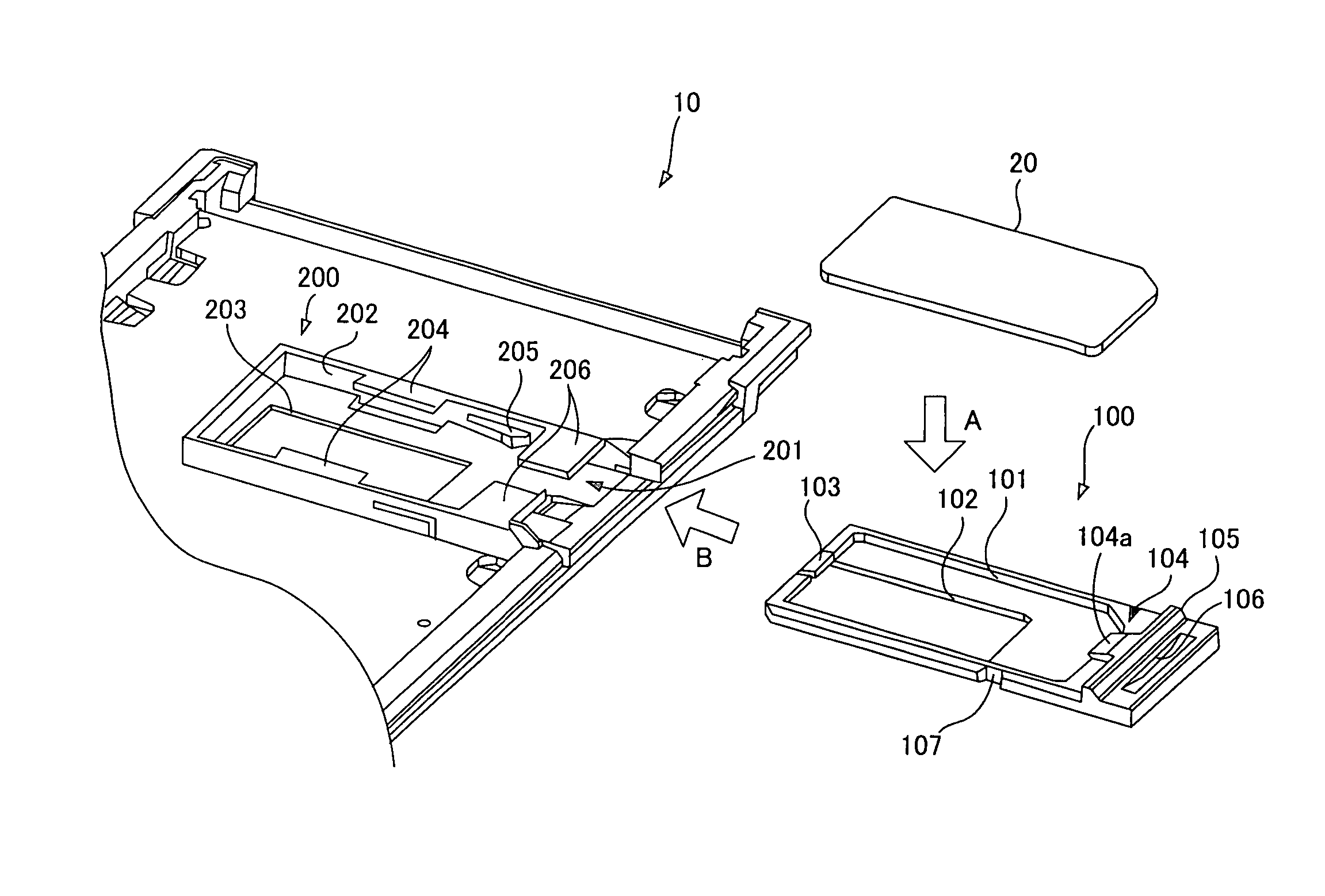
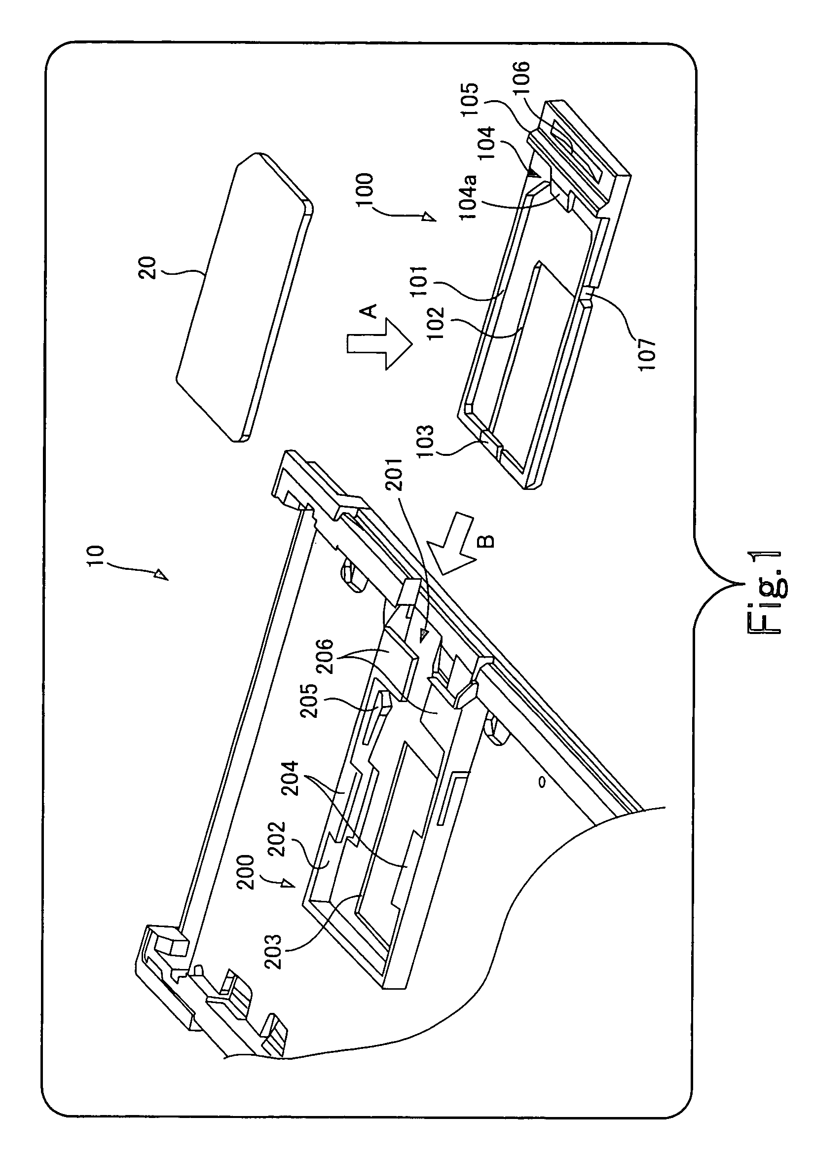
[0043]FIG. 1 is a perspective view of a card-type terminal according to the present invention, showing those parts which are characteristic of the present invention.
[0044]The figure shows a card-type terminal 10 equipped with a tray 100 and a guide 200 as well as shows a memory card 20 installed in the card-type terminal.
[0045]To install the memory card 20 in the card-type terminal 10, the user mounts the memory card 20 on the tray 100 (arrow A) and slides the tray 100, with the memory card 20 mounted, into the guide 200 along arrow B.
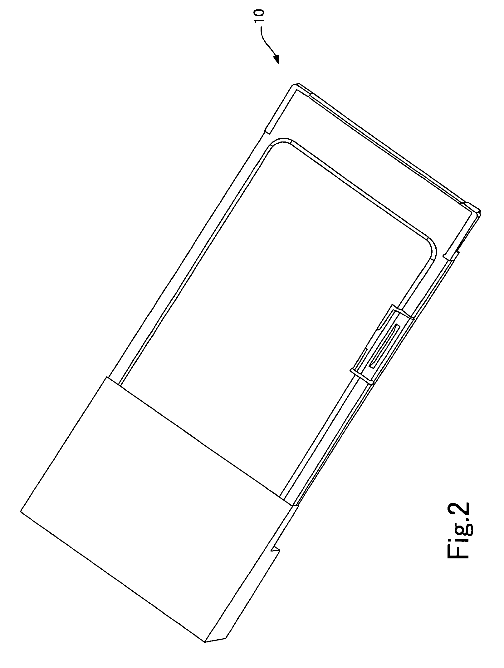
[0046]FIG. 2 is an external perspective view of the card-type terminal (on the side of a memory card loading slot) while FIG. 3 is an external perspective view of the card-type terminal, showing the side opposite to the one shown in FIG. 2.
[0047]FIGS. 4, 5, and 6 are perspective views showing, respectively, the main body of the card-type terminal with the memory card fully inserted, with the memory card withdrawn halfway, and with the memory card withd...
second embodiment
[0069]FIG. 12 is a plan view showing a guide in a card-type terminal according to the present invention with a tray inserted in the guide while FIG. 13 is a sectional view taken along arrow B–B′ in FIG. 12.
[0070]As shown in FIG. 13, the tray 100 has concave portions 118 formed in its flanks and extending in the insertion direction. On the other hand, the guide 200 has convex portions 217 formed on the side of the tray housing 202 (see FIG. 1). They extend in the insertion direction and slidably fit in the concave portions 118 of the tray 100.
[0071]According to the second embodiment, the concave portions 118 in the flanks of the tray 100 and the convex portions 217 on the side of the tray housing 202 of the guide 200 compose a misinsertion prevention mechanism which prevents the tray 100 from being inserted upside down into the guide 200.
[0072]In this way, the concave portions and convex portions which fit in the concave portions may be provided on whichever of the tray and guide.
third embodiment
[0073]FIG. 14 is a plan view showing a guide in a card-type terminal according to the present invention with a tray inserted in the guide while FIG. 15 is a sectional view taken along arrow C–C′ in FIG. 14.
[0074]As shown in FIG. 14, the tray 100 has concave portions 121 formed in it and extending in the insertion direction. On the other hand, the guide 200 has convex portions 221 which fit in the concave portions 121. The convex portions 221 do not extend in the insertion direction. They are cylindrical bosses or the like which protrude downward from the guards 206. When the tray 100 is pulled out from the guide 200, the convex portions 221 hit a forward-end wall 121a of the concave portions 121 before the tray 100 is pulled out completely, preventing the tray 100 from being pulled out of the guide 200 any more.
[0075]Instead of the misinsertion prevention mechanism which prevents the tray from being inserted upside down (described with reference to FIGS. 10 to 13), a safety catch ma...
PUM
 Abstract
Description
Claims
Application Information
 - R&D
- Intellectual Property
- Life Sciences
- Materials
- Tech Scout
- Unparalleled Data Quality
- Higher Quality Content
- 60% Fewer Hallucinations
Browse by: Latest US Patents, China's latest patents, Technical Efficacy Thesaurus, Application Domain, Technology Topic, Popular Technical Reports.
© 2025 PatSnap. All rights reserved.Legal|Privacy policy|Modern Slavery Act Transparency Statement|Sitemap|About US| Contact US: help@patsnap.com


