High-pressure sealing

Inactive Publication Date: 2006-10-17
MLC EXTRUSION SYST
View PDF22 Cites 6 Cited by
  • Summary
  • Abstract
  • Description
  • Claims
  • Application Information

AI Technical Summary

Benefits of technology

[0013]According to the design of the present invention, the metallic rings of the high-pressure subassembly are not subjected to significant bending deformations, and the resilient ring of the low-pressure subassembly does not wear excessively under high pressure, thereby allowing for longer operational life and efficiency of the seal assembly and operability at much higher pressures than the prior art seals.

Problems solved by technology

Existing high-pressure seal assemblies usually include elements made of resilient material which, when interacting with the plunger and other metal parts, are subjected to rapid wear.
There are other high-pressure seal designs, where the operation of the high-pressure subassembly does not involve rapid wear of the low-pressure subassembly, but then the high-pressure subassembly experiences too large elastic deformations leading to rapid wear.

Method used


Image

  • High-pressure sealing
  • High-pressure sealing
  • High-pressure sealing

Examples


Embodiment Construction

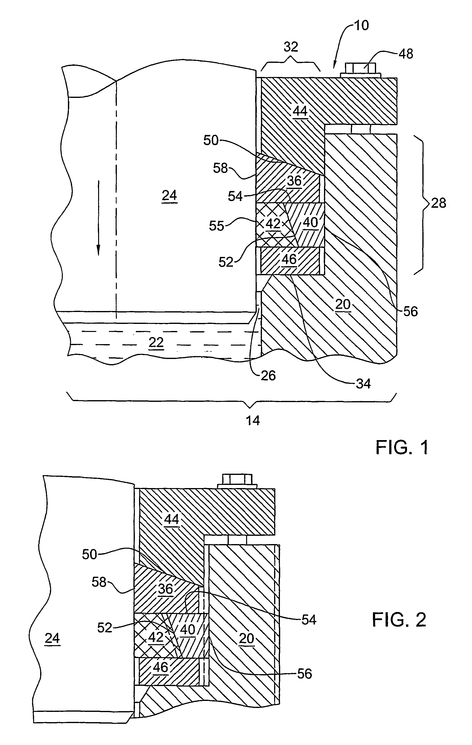
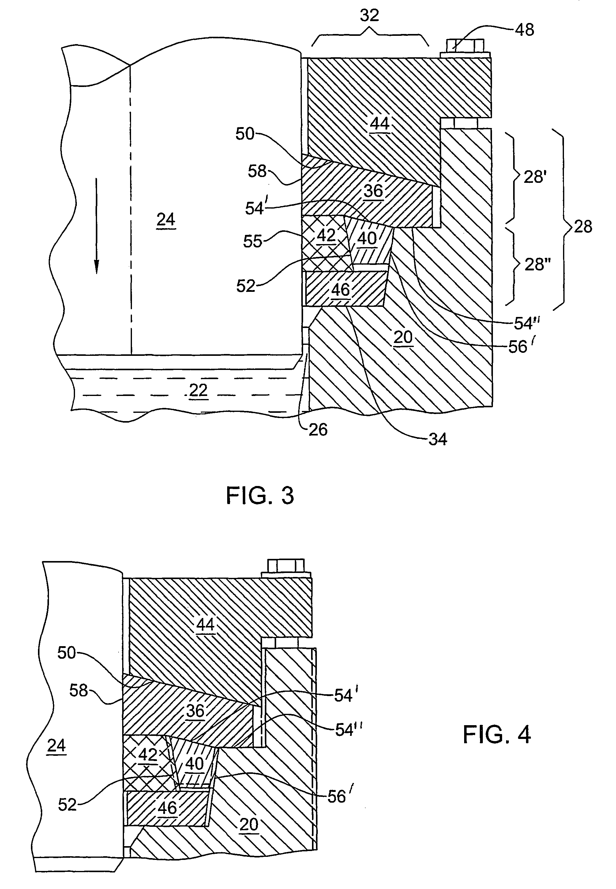
[0019]With reference to FIG. 1, it is shown a high-pressure seal assembly 10 in accordance with the present invention, in a high-pressure cylinder 14 with wall 20, hydraulic working liquid 22 and plunger 24 axially moveable into the cylinder to compress the working liquid. The seal assembly is designed to seal the gap 26 between the wall 20 and the plunger 24, and is disposed in an annular internal recess 28 in the wall 20, the recess being bounded radially by the cylinder wall and axially by an open end 32 and a bottom 34 opposite thereto. The seal assembly comprises a metallic plunger-sealing ring 36, a metallic cylinder-sealing ring 40, a resilient low-pressure ring 42, an annular seal holder 44, and a supporting ring 46. The supporting ring 46 is disposed at the recess bottom 34. It has no sealing function and can be regarded as part of the bottom 34 in the cylinder wall 20. The seal holder 44 is tightened axially by suitable means 48 to the cylinder wall 20, thereby urging elem...


PUM


Abstract

In a high-pressure cylinder with an axial plunger, a seal assembly for scaling the gap between the cylinder wall and the plunger. The assembly is disposed in an annual recess in the wall having an open end and a bottom opposite thereto, and comprises a plunger-sealing ring, a cylinder-sealing ring, a resilient low-pressure ring, and an annual seal holder. The seal holder urges the plunger-sealing ring against the cylinder-sealing ring and the low-pressure ring, and urges the latter two rings against the recess bottom and against each other. The plunger-sealing ring and the cylinder-sealing ring are metallic, their mutual contact surfaces are fitted to each other, and the plunger-sealing ring has sufficient section modulus to ensure that under high pressure the contact and bending deformations at the mutual contact surfaces will be sufficiently small as to keep a tight fit therebetween.

Description

FIELD OF THE INVENTION[0001]This invention generally relates to methods of sealing a plunger moveable in a cylinder, and more particularly, in a high-pressure hydraulic cylinder.BACKGROUND OF THE INVENTION[0002]Pressing and extrusion under very high hydrostatic pressure is an efficient method of processing metals and other materials. Hydraulic presses and cylinders of ever growing power are introduced in metal working and other industries. High-pressure devices need seas capable to work under a wide range of pressures, from atmospheric pressure to extremely high pressures of 20–40 Kbar and more, at which the internal diameter of the high-pressure cylinder expands by ˜1% and more.[0003]A hydraulic cylinder has a cylinder wall with an open end wherein a plunger enters the cylinder to compress a hydraulic liquid to high pressure levels. A seal assembly is disposed in an annular recess in the cylinder wall near the open end. Usually, a high-pressure seal assembly comprises a high-pressu...

Claims


Application Information

Patent Timeline
IPC IPC(8): F16J15/18F16J15/28F16J15/56
CPCF16J15/184F16J15/56
Inventor LUGOVSKOY, VICTORMAGAZINER, VLADIMIRCHERTKOV, VITALYDANIELI, GUY
Owner MLC EXTRUSION SYST
Why Eureka
Try Eureka