
Image forming apparatus

a technology of forming apparatus and forming roller, which is applied in the direction of electrographic process apparatus, instruments, optics, etc., can solve the problems of hot offset, uneven fixed image, and direct contact between the upper and lower rollers of the fixing unit, so as to prevent an excessive heating of the upper roller and achieve stable printing

Inactive Publication Date: 2006-10-10
OKI DATA CORP
View PDF5 Cites 11 Cited by
  • Summary
  • Abstract
  • Description
  • Claims
  • Application Information

AI Technical Summary

Benefits of technology

[0007]An object of the present invention is to provide an image forming apparatus capable of preventing an excessive heating of rollers of a fixing unit and capable of ensuring stable printing.
[0014]With such an arrangement, when the image is fixed to one side of the recording medium, the other side of the recording medium can be prevented from being excessively heated, and therefore it becomes possible to perform a stable fixing operation without causing the degradation of the image.
[0015]Moreover, when the image is fixed to one side of the recording medium, the other side of the recording medium can be kept at a predetermined temperature corresponding to the thickness of the recording medium, and therefore it becomes possible to prevent a hot offset even when a thin recording medium is used, and to prevent a cold offset even when a thick recording medium is used.

Problems solved by technology

However, because of the above described time interval between two fixing operations, upper and lower rollers of the fixing unit directly contact each other and rotate with each other for a relatively long time.
Therefore, the fixed image may become uneven and a hot offset may occur.
Moreover, in a simplex printing in which the image is formed on only one side of the recording medium, if there is a relatively long time interval between fixing operations of the preceding recording medium and the subsequent recording medium, the lower roller may be excessively heated.
In such a case, the brightness of the image may be unstable, and the image quality may be degraded.

Method used


Image

  • Image forming apparatus
  • Image forming apparatus
  • Image forming apparatus

Examples


embodiment 1

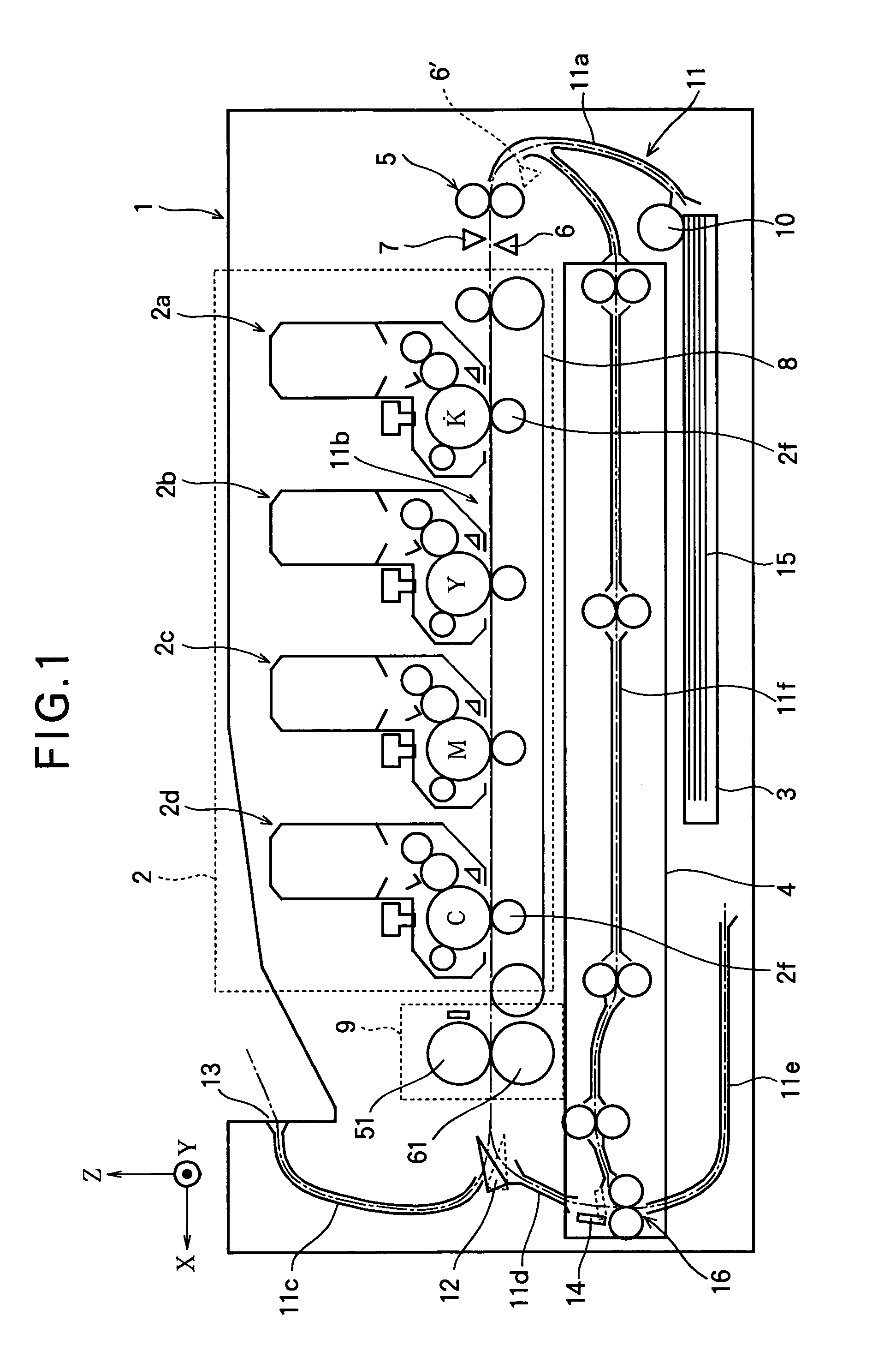
[0028]FIG. 1 is a schematic front view of an image forming apparatus according to Embodiment 1 of the present invention.

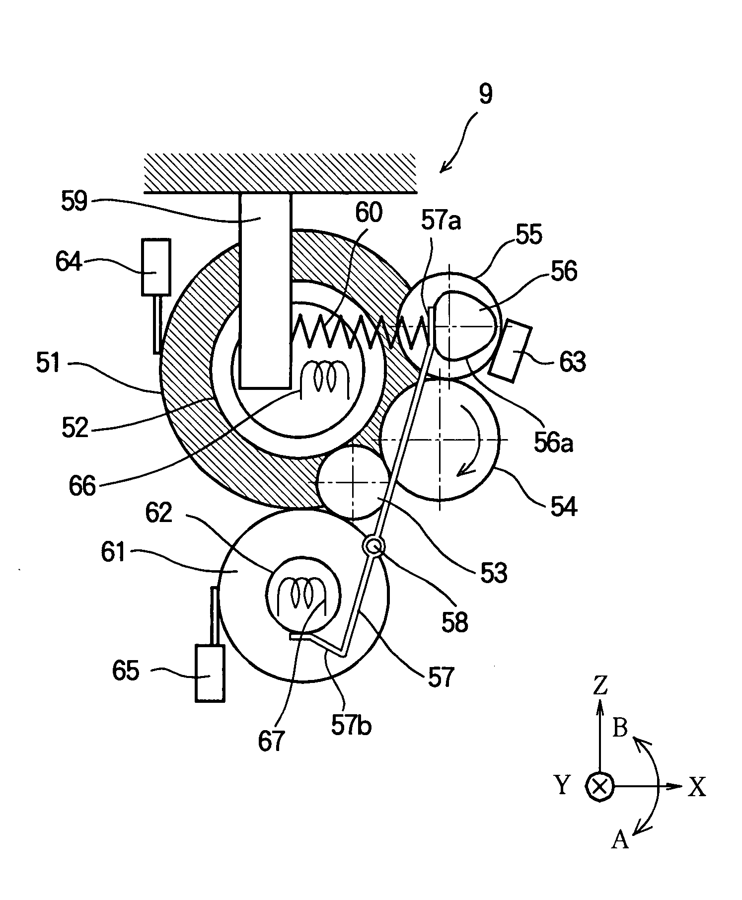
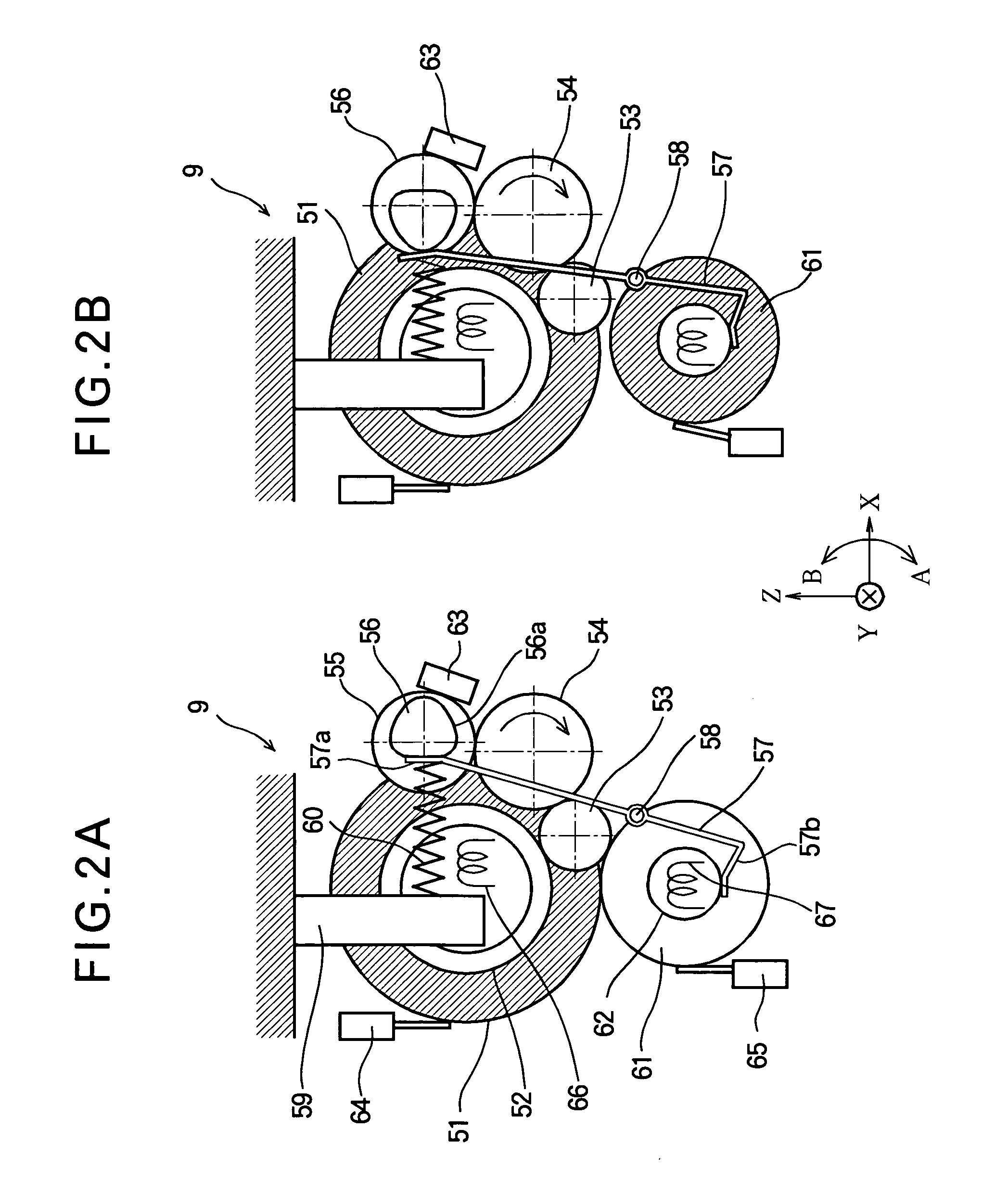
[0029]The image forming apparatus 1 includes a cassette mounting portion to which a feeding tray 3 is mounted. In the feeding tray 3, a stack of recording media 15 (for example, recording papers) is accommodated. The image forming apparatus 1 further includes a duplex feeding unit 4 that feeds the recording medium 15 along a feeding path 11 and turns the recording sheet 15 upside down. The image forming apparatus 1 further includes a print process unit 2 that feeds the recording medium 15 along a feeding path 11, and transfers a toner image to the recording medium 15. The image forming apparatus 1 further includes a fixing unit 9 that fixes the toner image to the recording medium 15.

[0030]The uppermost recording medium 15 of the stack accommodated in the feeding tray 3 is picked up by a hopping roller 10 and fed into a feeding path 11a. The leading edge of the reco...

embodiment 2

[0061]FIGS. 5A through 5F are timing charts illustrating the operation of the image forming apparatus according to Embodiment 2 of the present invention. With reference to FIGS. 5A through 5F, the operation of the image forming apparatus according to Embodiment 2 will be described.

[0062]The structure of the image forming apparatus of Embodiment 2 can be the same as that of the image forming apparatus 1 (FIG. 1) of Embodiment 1. The structure of the control unit 101 of the image forming apparatus of Embodiment 2 is the same as that of the image forming apparatus (FIG. 3) of Embodiment 1. Only a part of the operation of the control unit 101 of Embodiment 2 is different from that of Embodiment 1. Therefore, FIGS. 1 through 3 are referred in the description of Embodiment 2.

[0063]In the printing operation, the processes from time t1 (i.e., when the medium detection sensor 6 detects the leading edge of the recording medium 15) to time t5 (i.e., when the fixing operation is completed and t...

embodiment 3

[0074]FIGS. 6A through 6F are timing chart illustrating the operation of the image forming apparatus according to Embodiment 3 of the present invention. With reference to FIGS. 6A through 6F, the operation of the image forming apparatus of Embodiment 3 will be described.

[0075]The structure of the image forming apparatus of Embodiment 3 can be the same as that of the image forming apparatus 1 (FIG. 1) of Embodiment 1. The structure of the control unit of the image forming apparatus of Embodiment 3 is the same as that of the image forming apparatus of Embodiment 1 (FIG. 3). Only a part of the operation of the control unit 101 in Embodiment 3 is different from that in Embodiment 1. Therefore, FIGS. 1 through 3 are referred in the description of Embodiment 3. In addition, the description will be made to the continuous printing in the simplex printing mode, and therefore the path selection guide 12 is set to a position indicated by the dashed line in FIG. 1.

[0076]When the printing operat...


PUM


Abstract

In a duplex printing or a simplex printing, upper and lower rollers of a fixing unit are separated from each other or stop rotating during a period after the fixing operation of the first side of a recording medium (or a preceding recording medium) and before the fixing operation of the second side of the recording medium (or a subsequent recording medium). With such an arrangement, it is possible to prevent the excessive heating of the lower roller, and thereby to prevent the degradation of the printed image.

Description

BACKGROUND OF THE INVENTION[0001]This invention relates to an image forming apparatus, and particularly to an arrangement for fixing a recording material such as toner to a recording medium.[0002]In an image forming apparatus, a recording material such as toner, ink or the like is used to form an image on a recording medium such as a paper. The recording medium with the image formed thereon is nipped by heated rollers so that the recording material is fixed to the recording medium. There is a type of image forming apparatus that has a duplex printing function, i.e., a function to form images on both sides of the recording medium.[0003]In the image forming apparatus of this type, a plurality of recording media with no image formed thereon are stacked in a feeding tray. The recording medium is fed from the feeding tray to an image forming unit, and an image is transferred to a first side of the recording medium. The recording medium is then fed to a fixing unit, and the image is fixed...

Claims


Application Information

Patent Timeline
Patent Type & Authority Patents(United States)
IPC IPC(8): G03G15/20G03G15/00
CPCG03G15/2032G03G2215/20G03G2215/2083
Inventor WATABE, TOMONORI
Owner OKI DATA CORP
Learn More