
Reinforcing bar connection and method

a technology of reinforcement bars and connections, applied in the direction of rod connections, couplings, manufacturing tools, etc., can solve the problems of affecting the fatigue or ultimate strength properties of the bar, requiring great skill, and affecting the connection angle, so as to prevent undue penetration of the bar, reduce the friction coefficient, and reduce the friction coefficient

Inactive Publication Date: 2006-10-10
ERICO INT
View PDF42 Cites 16 Cited by
  • Summary
  • Abstract
  • Description
  • Claims
  • Application Information

AI Technical Summary

Benefits of technology

[0005]A reinforcing bar connection for concrete construction utilizes a contractible jaw or assembly which is closed around aligned bar ends to form the joint and tightly grip the bars. The jaw assembly is closed from each axial end to constrict around and bridge the ends of end-to-end reinforcing bars. The jaws of the assembly have teeth which bite into the ends of the bar. The assembly is constricted by forcing self-locking taper sleeves or collars over each end which hold the jaw constricted locking the bars together. The teeth are designed to bite into the ribs or projecting deformations on the surface of the bar which forms the overall diameter, but not bite into the core or nominal diameter of the bar. In this manner, the splice does not affect the fatigue or ultimate strength properties of the bar while providing a low slip connection. The jaw segments may be held assembled by a frangible plastic frame. The configuration of the jaws limits the contraction and precludes undue penetration of the bar by the teeth. The connection or splice has high tensile and compressive strength and will pass the dynamic cycling and / or fatigue requirements to qualify as a Type 2 coupler. No bar end preparation or torque application is required to make the coupling. In the method, the closing and locking occur concurrently with a simplified tool to enable the splice to be formed easily and quickly.

Problems solved by technology

The bar ends are of course axially offset which creates design problems, and eccentric loading whether compressive or tensile from bar-to-bar.
Welding is suitable for some bar steels but not for others and the heat may actually weaken some bars.
Done correctly, it requires great skill and is expensive.
Such mechanical splices don't necessarily have high compressive and tensile strength, nor can they necessarily qualify as a Type 2 mechanical connection where a minimum of five couplers must pass the cyclic testing procedure to qualify as a Type 2 splice in all United States earthquake zones.

Method used


Image

  • Reinforcing bar connection and method
  • Reinforcing bar connection and method
  • Reinforcing bar connection and method

Examples


Embodiment Construction

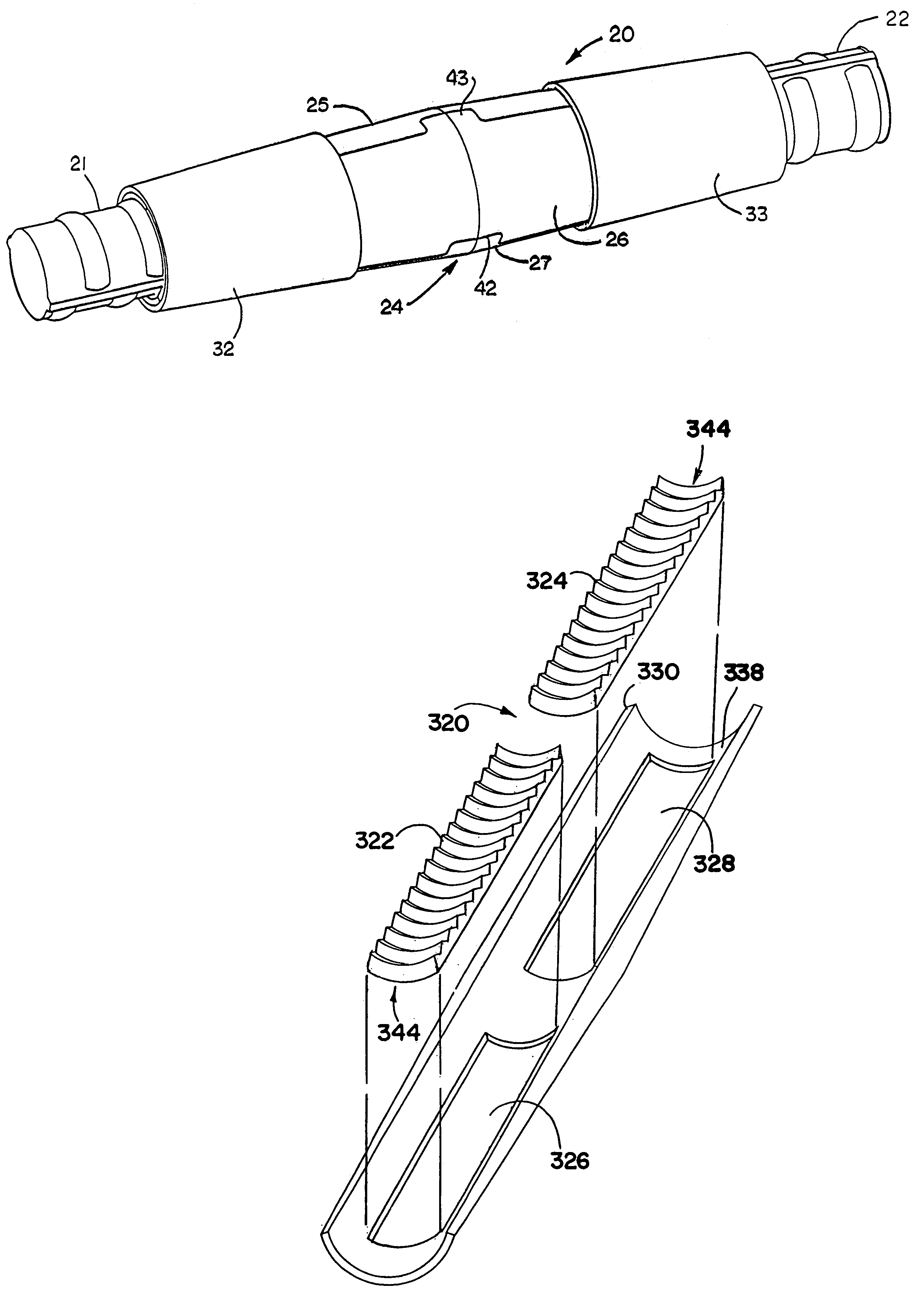
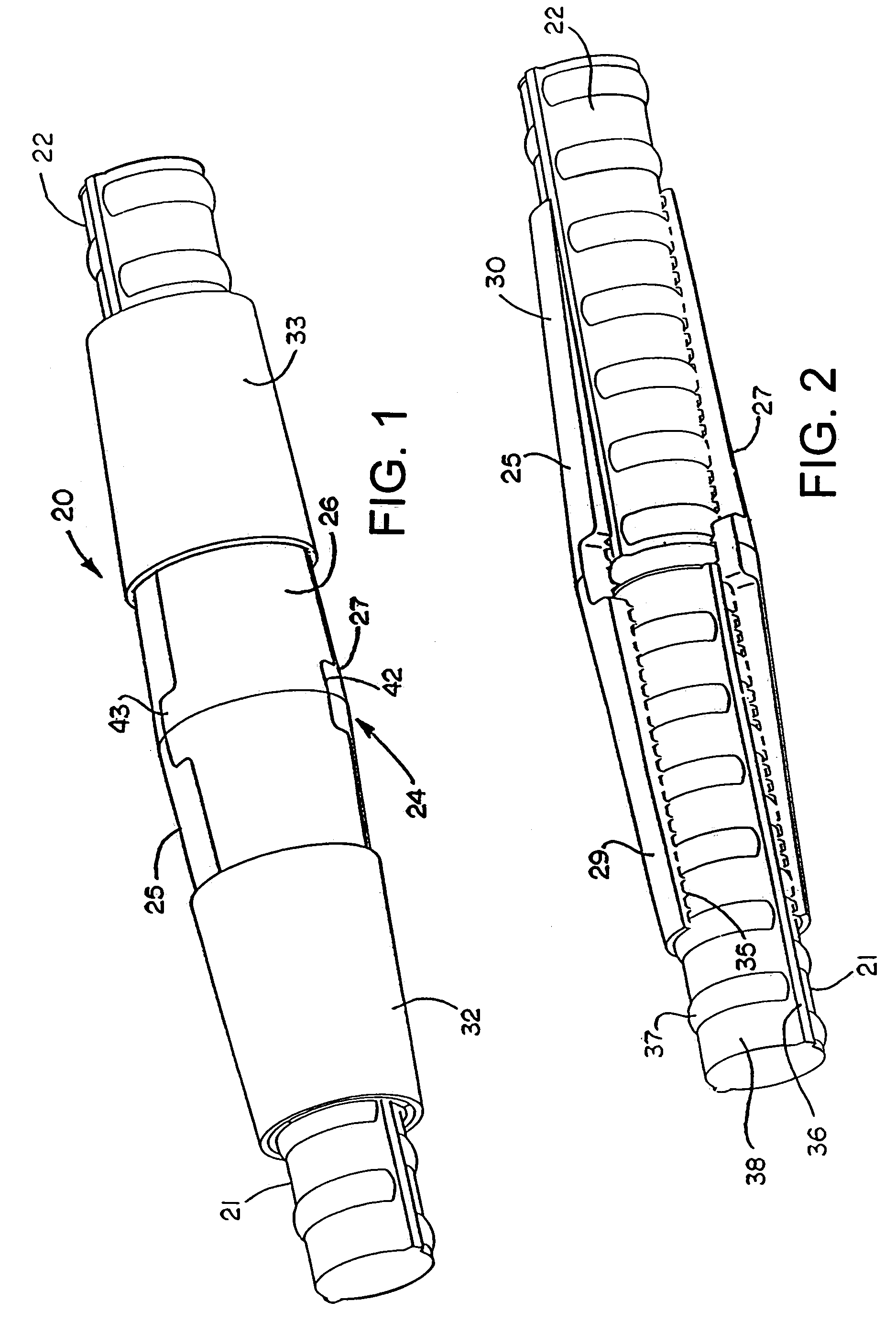
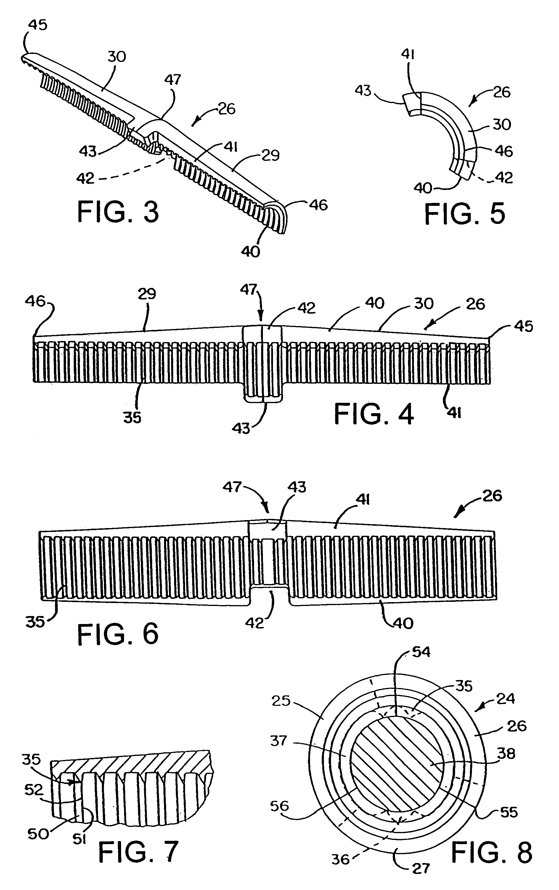
[0053]Referring initially to FIGS. 1 and 2, there is illustrated a reinforcing bar connection in accordance with the present invention shown generally at 20 joining end-to-end axially aligned deformed reinforcing bars 21 and 22. The reinforcing bars are shown broken away so that only the ends gripped by the splice or connection are illustrated. It will be appreciated that the bars may extend to a substantial length and may either be vertical, horizontal, or even diagonal in the steel reinforced concrete construction taking place. The connection and bars are designed to be embedded in poured concrete. The connection comprises a jaw assembly shown generally at 24, which includes three circumferentially interfitting three jaw elements shown at 25, 26 and 27. It will be appreciated that alternatively two jaw elements or more than three jaw elements may form the assembly 24.

[0054]As seen more clearly in FIG. 2, the exterior of the jaw elements forms oppositely tapering shallow angle surf...


PUM


Abstract

A high strength reinforcing bar splice uses a contractible jaw assembly bridging the bar ends to be joined. The jaw assembly includes interior teeth designed to bite into the projecting ribs or deformations on the outside of the bar ends which form the overall diameter of the bar but not the core or nominal diameter of the bar. The jaw assembly is constricted from both axial ends by driving tapered locking collars on each end of the jaw assembly with a tool while concurrently causing the jaw assembly to constrict and bite into the bar ends. When the tool is removed, the collars remain in place locking the jaw assembly closed. The splice provides not only high tensile and compressive strengths but also has good fatigue and dynamic strength to qualify as a Type 2 coupler.

Description

[0001]This application is a continuation in part of U.S. application Ser. No. 10 / 055,551, filed Jan. 23, 2002, now U.S. Pat. No. 6,719,478 which claims priority under 35 USC 119(e) of U.S. Provisional Application No. 60 / 263,860, filed Jan. 23, 2001. Both of the preceding applications are hereby incorporated by reference in their entireties.TECHNICAL FIELD[0002]This invention relates generally as indicated to a reinforcing bar connection, and more particularly to a high strength reinforcing bar splice which provides not only high tensile and compressive strengths, but also has the dynamic and fatigue characteristics to qualify as a Type 2 coupler approved for all United States earthquake zones. The invention also relates to a method of making the connection.BACKGROUND OF THE INVENTION[0003]In steel reinforced concrete construction, there are generally three types of splices or connections; namely lap splices; mechanical splices; and welding. Probably the most common is the lap splice...

Claims


Application Information

Patent Timeline
IPC IPC(8): F16B2/14B25B27/10E04C5/16E04G21/12
CPCB25B27/10E04C5/165E04G21/122Y10T403/7064Y10T403/5793Y10T403/5733Y10T403/5766Y10T403/7054
Inventor GREGEL, JOHN J.KERKAY, COLLEEN M.SAMAS, MARK V.TH. MAAS, WILHELMUS G.COLARUSSO, LOUIS J.
Owner ERICO INT
Learn More