Magnet structure
a magnetic structure and magnet technology, applied in the field of magnet structures, can solve the problems of limited imaging applications, limited application of this design, and insufficient scanning field strength to adequately image the target body part, and achieve the effect of reducing magnetic reluctan
- Summary
- Abstract
- Description
- Claims
- Application Information
AI Technical Summary
Benefits of technology
Problems solved by technology
Method used
Image
Examples
first exemplary embodiment
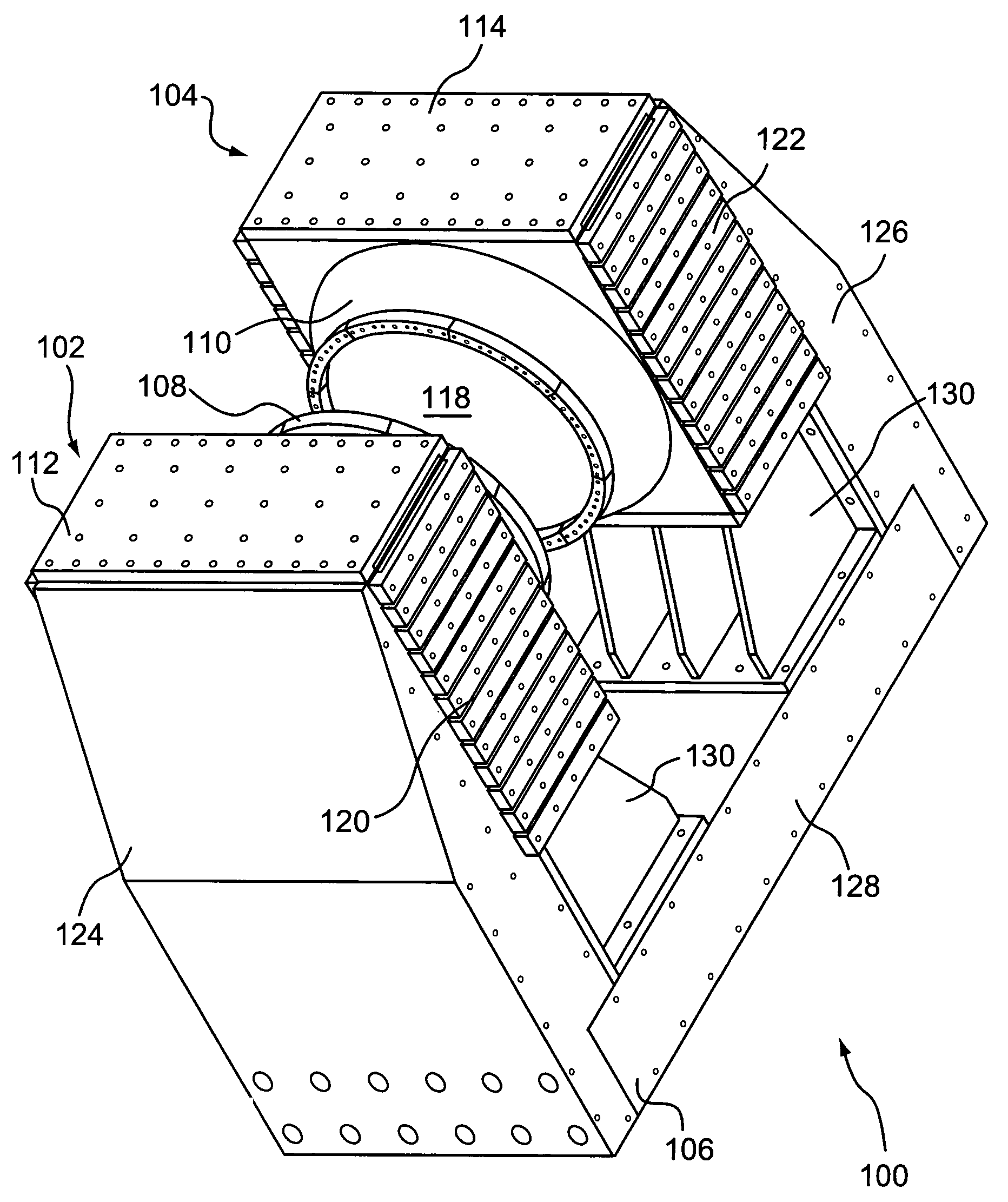
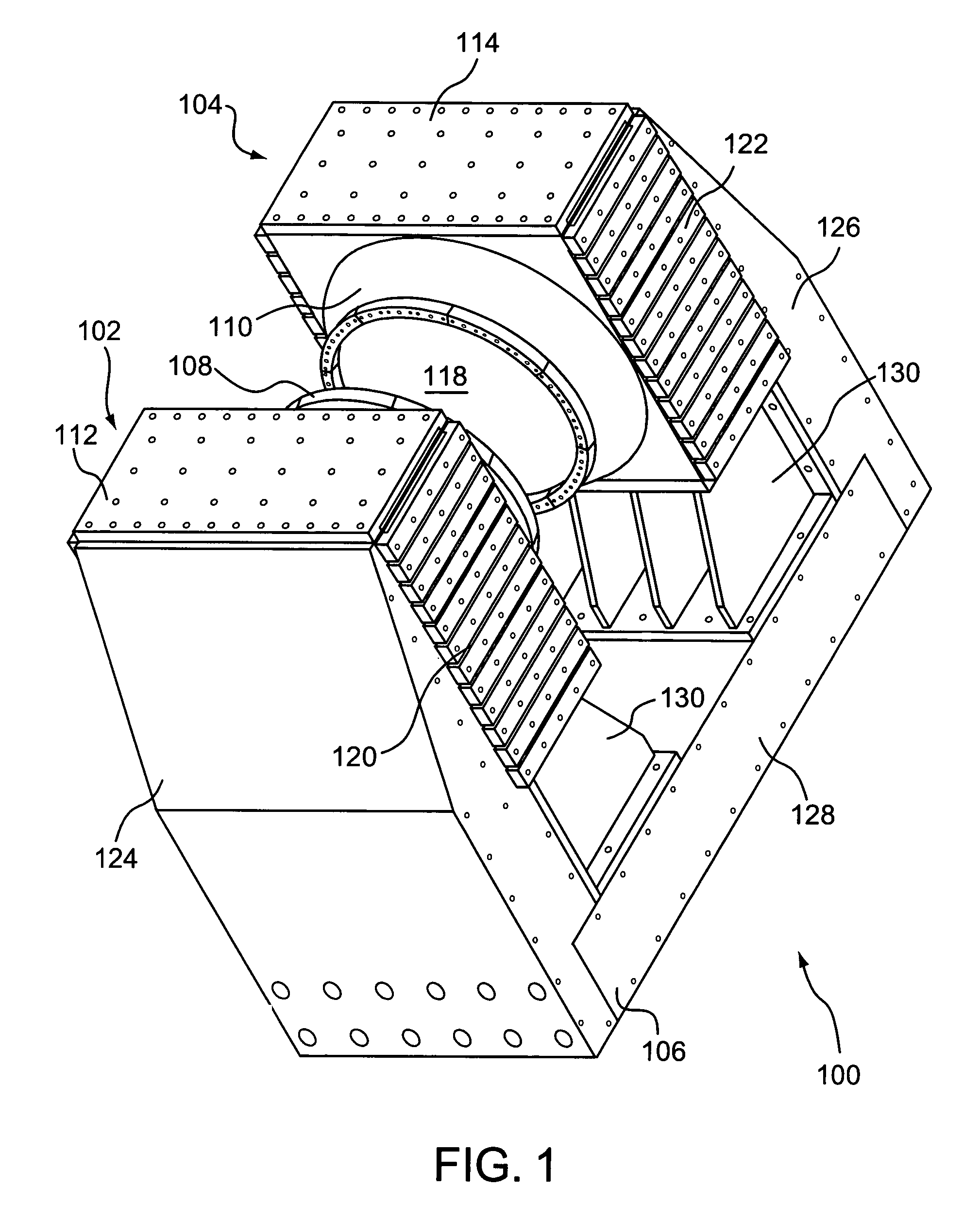
[0057]A first exemplary embodiment of the invention is shown in FIGS. 1-6. FIG. 1 is an isometric view of the magnet structure 100 of this exemplary embodiment. The magnet structure 100 includes a pair of magnet assemblies 102, 104, and a frame 106, which provides support for the first and second magnet assemblies 102, 104 and maintains a fixed distance between them. Although the frame 106 satisfies structural requirements of the magnet structure 100, certain components of the frame 106 can perform functional roles as well.
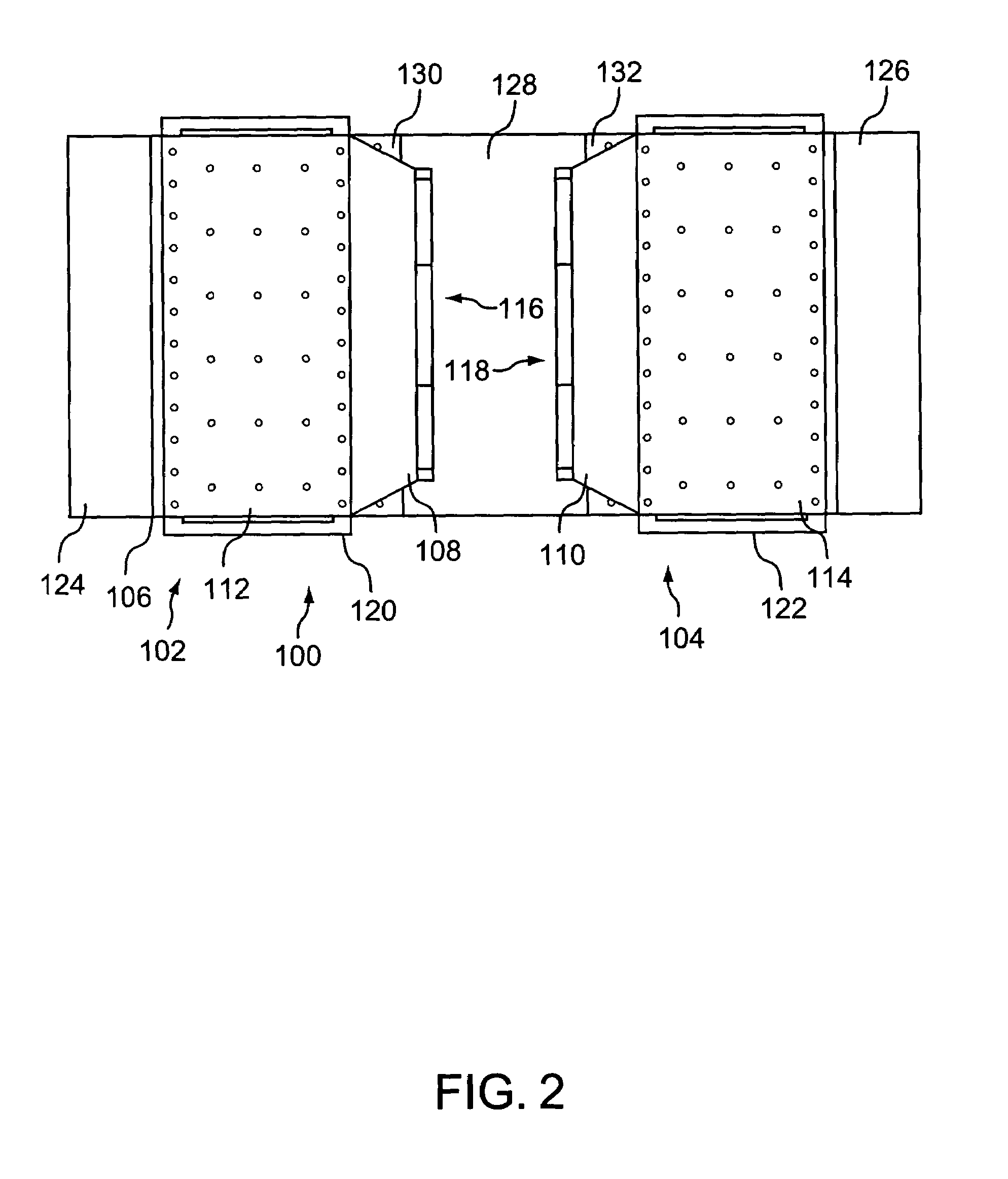
[0058]The first and second magnet assemblies 102, 104 include respective first and second poles 108, 110 and respective first and second magnet enclosures 112, 114. As shown in FIG. 3, the poles 108, 110 are disposed on opposing sides of the magnet enclosures 112, 114, such that faces 116, 118 of the poles 112,114 are substantially parallel and facing each other. The magnet enclosures 112, 114 are filled with magnetic material, which is the magnetic mass that prov...
second exemplary embodiment
[0062]FIGS. 7-10 illustrate a second exemplary embodiment of the magnet structure 200 of the present invention. As in the first embodiment, the magnet structure 200 includes a pair of magnet assemblies 202, 204, and a frame 206, which provides support for the first and second magnet assemblies 202, 204 and maintains a fixed distance between them. Although the frame 206 satisfies structural requirements of the magnet structure 200, certain components of the frame 206 can perform functional roles as well.
[0063]The first and second magnet assemblies 202, 204 include respective first and second poles 208, 210 and respective first and second magnet enclosures 212, 214. As shown in FIGS. 7 and 8, the poles 208, 210 are disposed on opposing sides of the magnet enclosures 212, 214, such that faces 216, 218 of the poles 208, 210 are substantially parallel and facing each other. The magnet enclosures 212, 214 are filled with magnetic material, which is the magnetic mass that provides the magn...
third exemplary embodiment
[0072]A third exemplary embodiment of the present invention is shown in FIGS. 11-15. As shown in FIG. 11, the magnet structure 300 includes first and second opposing permanent magnet assemblies 302, 304, held in place and separated by a frame 306. The frame includes first and second frame ends 308, 310, to which the magnet assemblies 302, 304 are attached. The frame ends 308, 310 are separated by a number of spacers 312, which keep the opposing poles 314, 316 apart by a selected distance so as to form a gap therebetween that is suitable for the intended use of the magnet structure 300.
[0073]As shown in FIG. 12, each frame end 308, 310 is formed in the shape of a cross, that is, consisting of connected, transverse, or intersecting pieces forming a construction having four segments emanating from a common point, such that the segments are arranged at substantially right angles with respect to adjacent segments. Thus, the exemplary embodiment shown in FIGS. 11-14 utilizes frame ends ha...
PUM
| Property | Measurement | Unit |
|---|---|---|
| distance | aaaaa | aaaaa |
| distance | aaaaa | aaaaa |
| distance | aaaaa | aaaaa |
Abstract
Description
Claims
Application Information
 - Generate Ideas
- Intellectual Property
- Life Sciences
- Materials
- Tech Scout
- Unparalleled Data Quality
- Higher Quality Content
- 60% Fewer Hallucinations
Browse by: Latest US Patents, China's latest patents, Technical Efficacy Thesaurus, Application Domain, Technology Topic, Popular Technical Reports.
© 2025 PatSnap. All rights reserved.Legal|Privacy policy|Modern Slavery Act Transparency Statement|Sitemap|About US| Contact US: help@patsnap.com


