
Field coverage configurable passive infrared radiation intrusion detection device

a detection device and infrared technology, applied in the direction of optical radiation measurement, instruments, nuclear engineering, etc., can solve the problems that the installer does not have the flexibility to reconfigure the field coverage of the device, and the infrared radiation intrusion detection device cannot be adjusted in the field during installation

Inactive Publication Date: 2006-10-03
INET CONSULTING
View PDF11 Cites 43 Cited by
  • Summary
  • Abstract
  • Description
  • Claims
  • Application Information

AI Technical Summary

Benefits of technology

The present invention provides two embodiments of a device that uses passive infrared radiation to detect intrusions in a field. The device has a plurality of sensors and an optical element to detect intrusion in different parts of the field. An electrical circuit activates or deactivates the sensors to configure the parts of the field that are covered by the device. The technical effect of this invention is to provide a flexible and effective way to detect intrusions in a field, which can help to improve security and prevent damage or unauthorized access.

Problems solved by technology

The technical problem addressed in this patent text is that current passive infrared radiation intrusion detection devices have a set coverage area and cannot be adjusted in the field during installation to take into account different heights or to avoid false alarms caused by heat sources.

Method used


Image

  • Field coverage configurable passive infrared radiation intrusion detection device
  • Field coverage configurable passive infrared radiation intrusion detection device
  • Field coverage configurable passive infrared radiation intrusion detection device

Examples


first embodiment

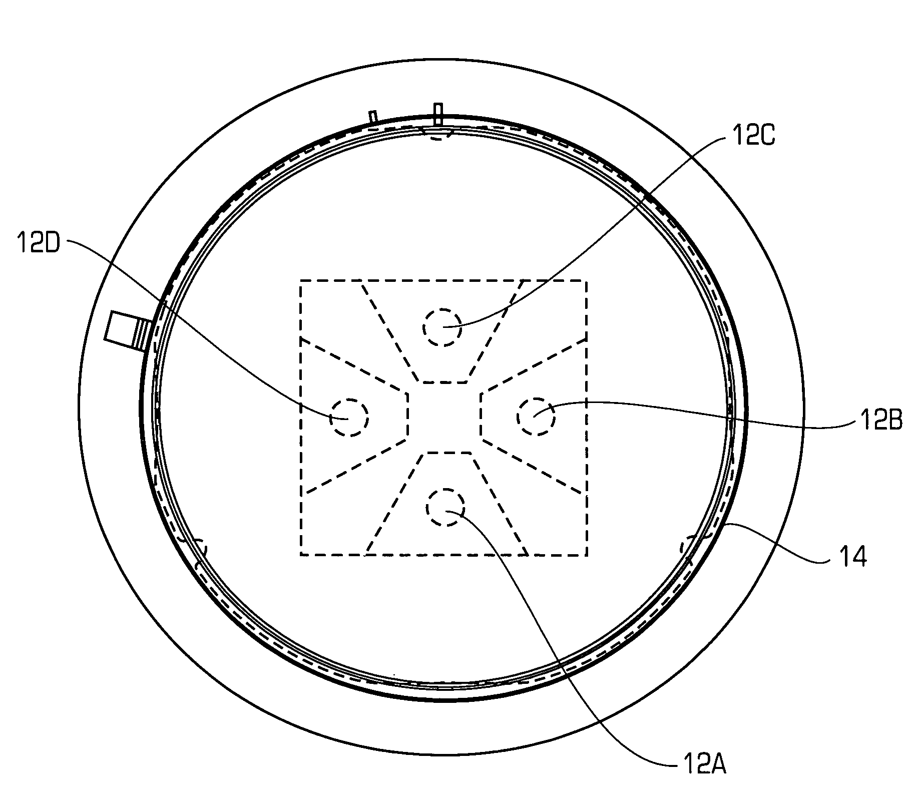
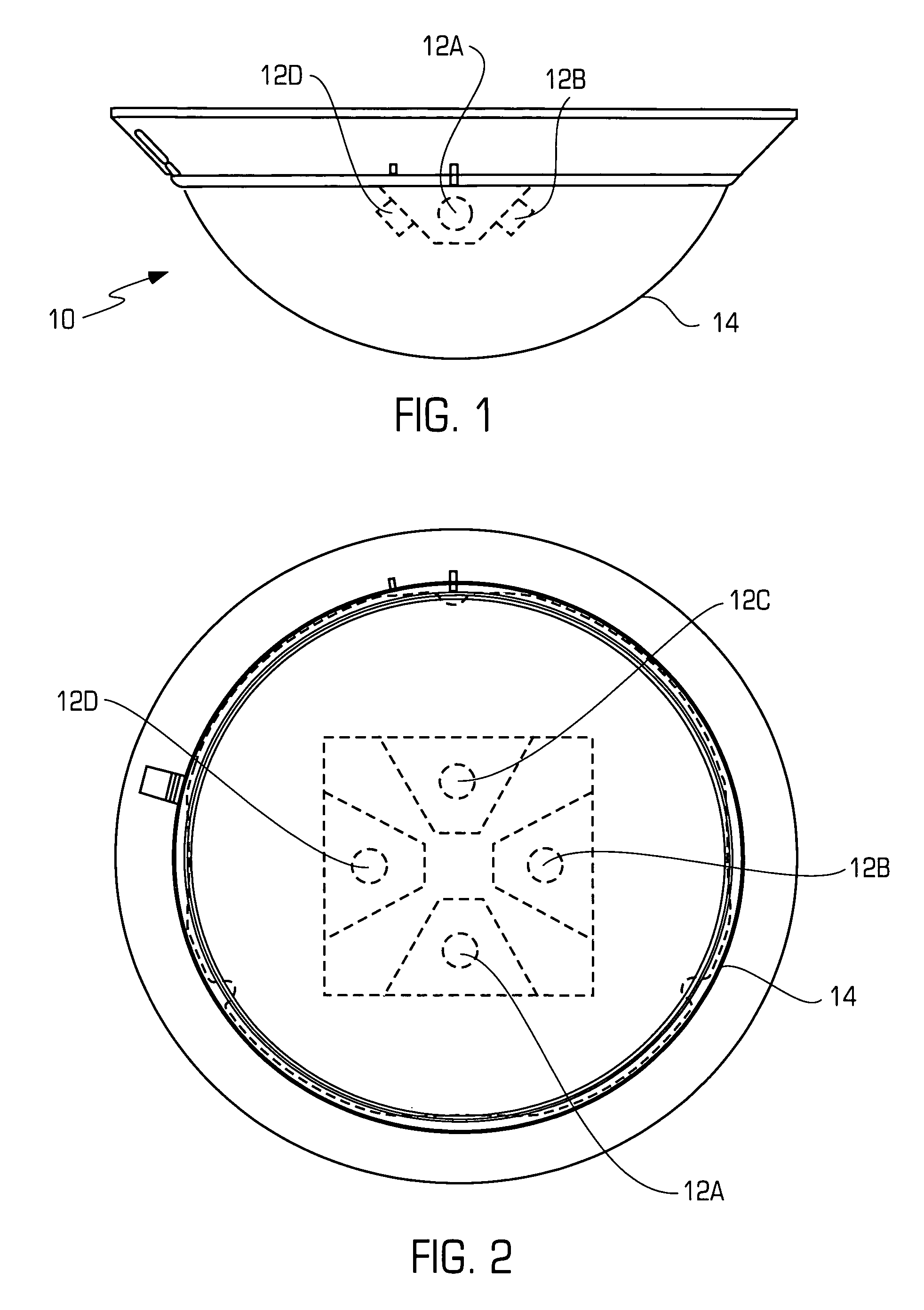
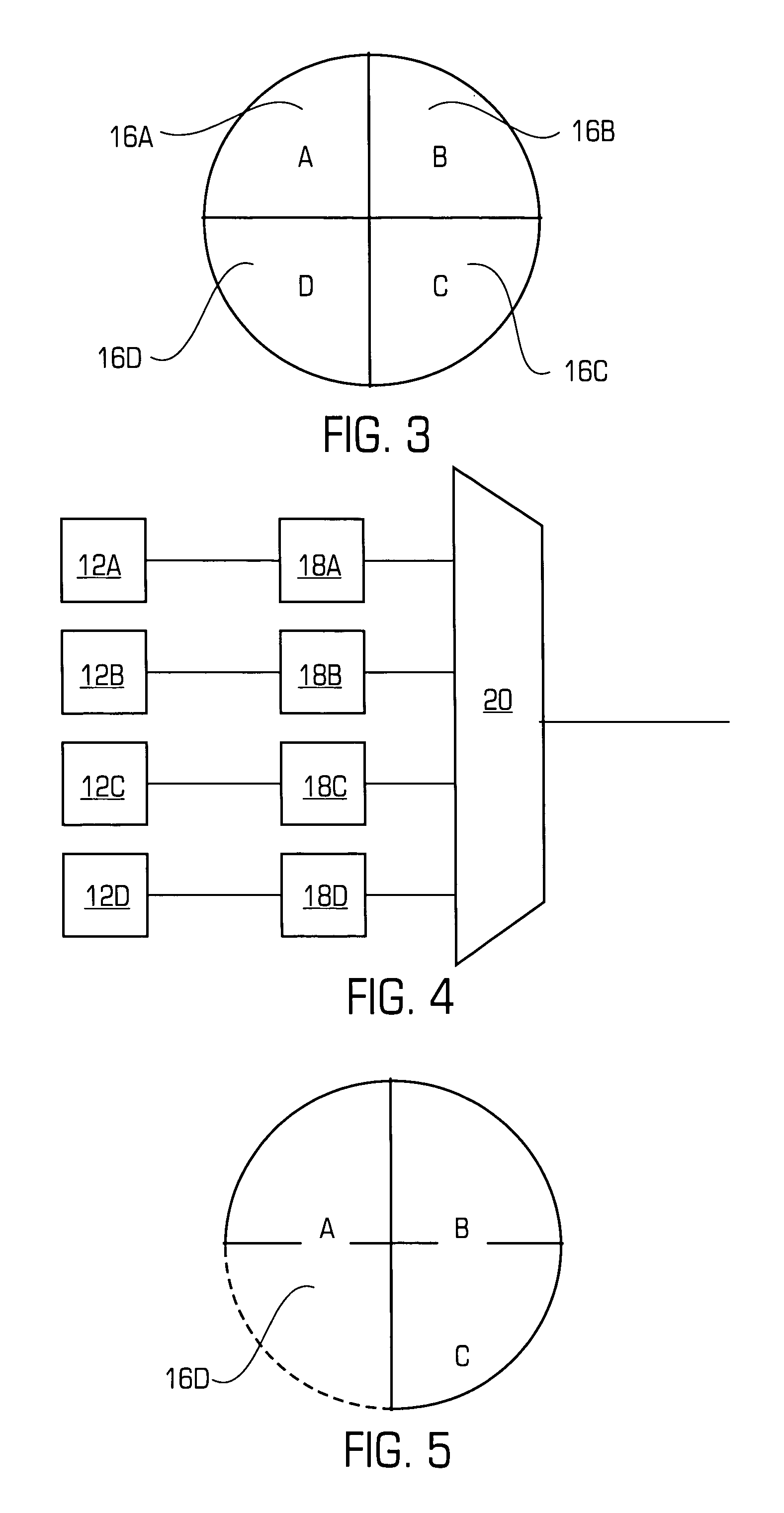
[0015]Referring to FIG. 1 there is shown a side view of a field coverage configurable passive infrared radiation intrusion detection device 10 of the present invention. The device 10 comprises a plurality of passive infrared radiation sensors (12A, 12B, 12C (shown in FIG. 2), and 12D). As shown in FIG. 2, each of the sensors 12 is positioned substantially in a rectilinear formation, i.e. spaced apart by approximately ninety (90) degrees. A single, hemispherically dome shaped, Fresnel lens or other optical element 14 surrounds the sensors 12 and gathers the infrared radiation from different portions 16(A–D) of the field and focuses them onto the plurality of sensors 12 (A–D). Of course, it is also within the scope of the present invention that the single optical element 14 can be replaced by a plurality optical elements with each optical element associated with a different passive infrared radiation sensor 12. As shown in FIG. 2, the optical element 14 is substantially hemisphericall...

second embodiment

[0019]Referring to FIG. 6A there is shown a detection device 110 of the present invention. The detection device 110 is similar to the detection device 10, shown in FIG. 1, and therefore like numerals will be used to describe same elements. Similar to the detection device 10, the detection device 110 comprises a plurality of passive infrared radiation sensors 12(A–D), but only elements 12A and 12C are shown, for illustration purposes. In addition, similar to the detection device 10, the detection device 110 comprises an optical element 14, which is a substantially hemispherically shaped dome, covering the sensors 12, for gathering infrared radiation from different portions of the field and focusing the infrared radiation onto the plurality of sensors 12. The radiation sensors 12 are mounted on a base plate 30. The hemispherically shaped optical element 14 is also mounted on the base plate 30. As shown in FIG. 6A, because the optical element 14 is hemispherically shaped, and is mounte...


PUM


Abstract

One embodiment of a field coverage configurable passive infrared radiation intrusion detection device comprises a plurality of passive infrared radiation sensors. The device also has an optical element for gathering infrared radiation from different portions of a field and for focusing said infrared radiation onto said plurality of passive infrared radiation sensors. An electrical activation/deactivation circuit receives the output of each passive infrared radiation sensor and selectively activates/deactivates one or more of the plurality of passive infrared radiation sensor outputs thereby configuring the portions of the field covered by the passive infrared intrusion detection device. In another embodiment of a field coverage configurable passive infrared radiation intrusion detection device, the height coverage of the device is adjustable in the field. The device comprises a passive infrared radiation sensor, and an optical element spaced apart from the passive infrared radiation sensor by a separation distance, for focusing infrared radiation from a field at a height distance from the optical element. The device further comprises means for changing the separation distance, thereby changing the height distance of the optical element from the field.

Description


Claims


Application Information

Patent Timeline
Owner INET CONSULTING
Learn More