
Method of manufacturing a magnetic head device

a manufacturing method and magnetic head technology, applied in the field of magnetic head devices, can solve the problems of too great deformation of output characteristics resulting from the existence of a magnetically degenerated layer to be ignored

Inactive Publication Date: 2006-10-03
WESTERN DIGITAL TECH INC
View PDF20 Cites 146 Cited by
  • Summary
  • Abstract
  • Description
  • Claims
  • Application Information

AI Technical Summary

Benefits of technology

[0012]A magnetic head device is disclosed. In one embodiment, the magnetic head device includes a slider having a side surface, a thin film magnetic head element formed by layering on the side surface and a magnetoresistance effect element included in the thin film magnetic head element. The magn...

Problems solved by technology

The magnetically degenerated layer is an extremely thin layer, of thickness approximately 1000 Å. However, due to the narrowing of the stripe heights of magnetoresistance effect elements with still greater increases in areal recording densities in recent years, the degradation of the output characteristic resulting from the existence of a the magnetically degenerated layer is becoming too great to be ignored.

Method used


Image

  • Method of manufacturing a magnetic head device
  • Method of manufacturing a magnetic head device
  • Method of manufacturing a magnetic head device

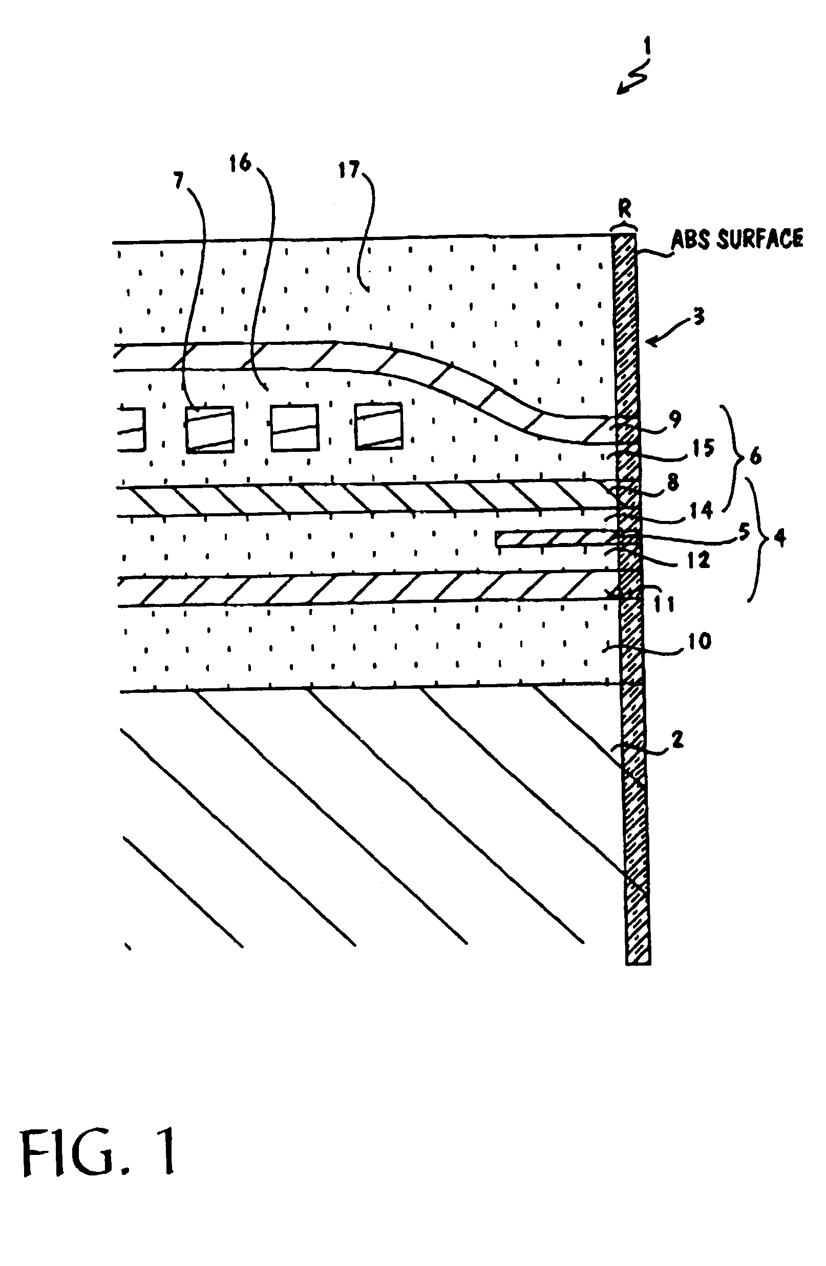
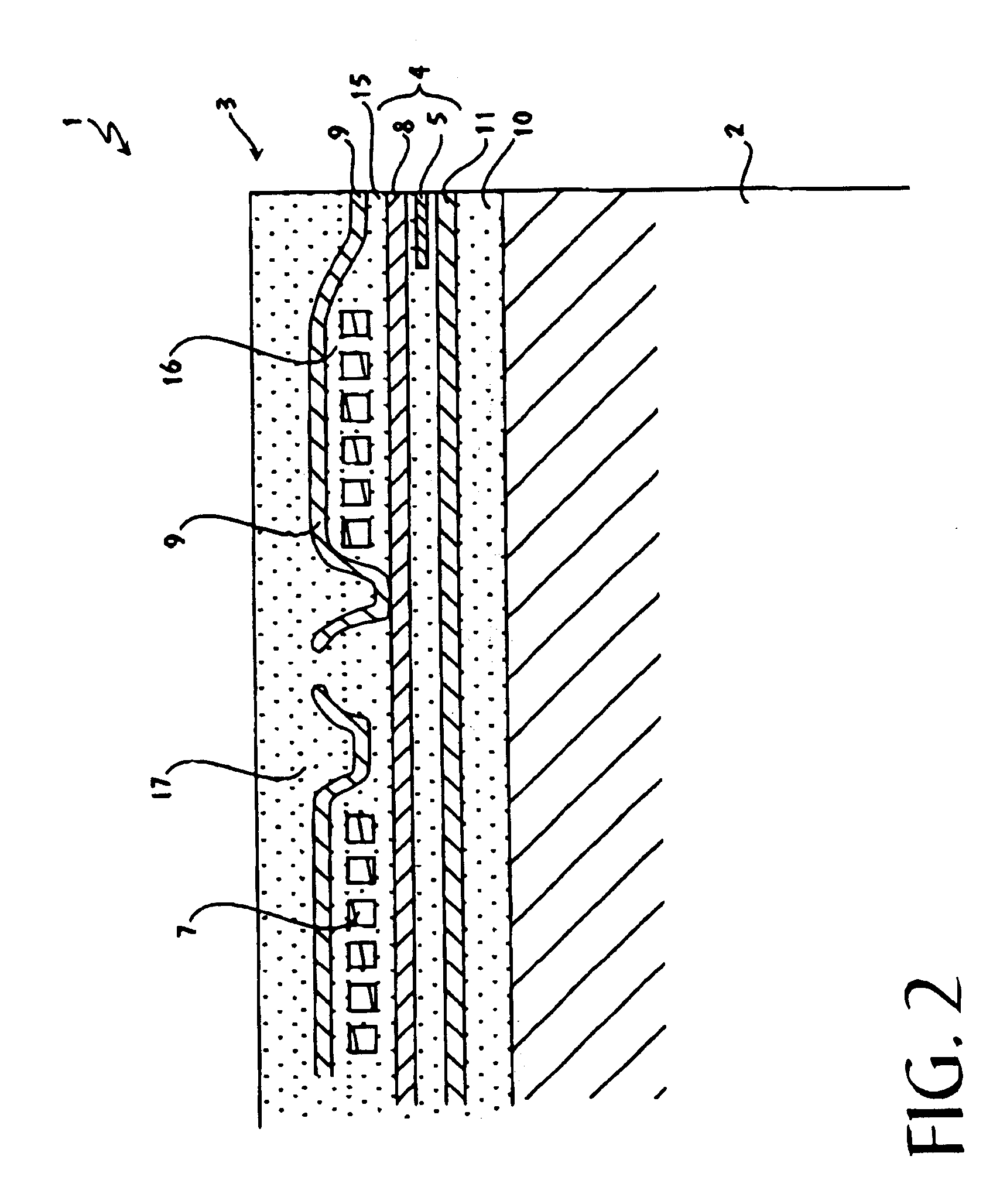
Examples


Embodiment Construction

[0025]In order to achieve the aforementioned objective, in this invention the following technical means was devised.

[0026]That is, in this invention, a magnetic head device, in which is formed by layering on one side surface of a slider a thin film magnetic head element having a magnetic reproduction element part principally comprised of a magnetoresistance effect element (MR element), and with the aforementioned magnetoresistance effect element exposed on the side opposing the magnetic recording media, is characterized by the removal by dry etching, at least over a region including the component parts of the thin film magnetic head element, of the magnetically degenerated layer produced on the exposed side of the magnetoresistance effect element by polishing of the surface opposing the magnetic recording media (that is, the ABS). After dry etching, the entire ABS may be coated with diamond-like carbon (“DLC”) or some other material.

[0027]By means of said magnetic head device, even ...


PUM

PropertyMeasurementUnit
Thicknessaaaaaaaaaa
Magnetismaaaaaaaaaa
Etch rateaaaaaaaaaa

Abstract

A method of manufacturing a magnetic head device includes forming a thin film magnetic head element over a substrate, the thin film magnetic head element including a magnetoresistance (MR) element. The substrate is cut such that the MR element is exposed on a side surface of the substrate. The side surface is then polished. Afterward, a magnetically degenerated layer is removed from the thin film magnetic head element along the side surface. It is emphasized that this abstract is provided to comply with the rules requiring an abstract that will allow a searcher or other reader to quickly ascertain the subject matter of the technical disclosure. It is submitted with the understanding that it will not be used to interpret or limit the scope or meaning of the claims.

Description

[0001]The present application is a Divisional of prior application Ser. No. 09 / 438,346, filed Nov. 11, 1999, now abandoned, entitled, “Magnetic Head Device, And Method Of Its Manufacture”.BACKGROUND OF THE INVENTION[0002]1. Field of the Invention[0003]This invention concerns a magnetic head device provided with a magnetoresistance effect-type thin film magnetic head element for reproduction, and the method for its manufacture.[0004]2. Background Information[0005]The magnetic head devices present in hard disk devices and other equipment are provided with a thin film magnetic head element on the trailing-side surface of a slider mounted on a suspension. The magnetic gap of the magnetic head element is exposed on a surface of the slider facing the media (called the air bearing surface or “ABS”) opposing the magnetic recording media. The magnetic head devices are used to perform magnetic recording of information onto and reproduction from magnetic disks or other magnetic recording media...

Claims


Application Information

Patent Timeline
IPC IPC(8): G11B5/127H04R31/00G11B5/187G11B5/31G11B5/39
CPCG11B5/3116G11B5/3903G11B5/3967G11B5/1871G11B5/3163Y10T29/49041Y10T29/49032Y10T29/49043Y10T29/49052Y10T29/49798Y10T29/49046Y10T29/49044Y10T29/49048Y10T29/49039
Inventor KUBOTA, KAZUYOSHIHAMAKAWA, MASAYUKI
Owner WESTERN DIGITAL TECH INC
Learn More